

-
Leon Zhang sales consultant
-
Email: zxl635973785@gmail.com
-
Phone/WhatsApp: +86 13655813266
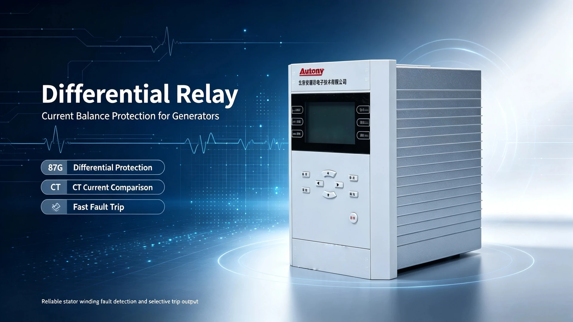
Differential Relay: Working Principle, Diagram, Types and Applications
Introduction
A differential relay (ANSI 87) is the most reliable unit protection device in modern power systems, widely deployed in industrial plants, utility substations and power generation stations. As a core differential protection relay, it delivers fast, selective and high-sensitivity fault isolation by monitoring current balance across a predefined electrical boundary. Unlike generic overcurrent protection, which responds only to current magnitude, the current differential relay judges faults based on current deviation between zone boundaries.
A core engineering principle distinguishes this device from conventional protection schemes: A differential relay protects a defined zone, not simply a piece of equipment. All protection behaviors, CT configurations and setting logics revolve around this fixed zone boundary, ensuring inherent selectivity for internal faults and stability for external system disturbances.
What Is a Differential Relay? (Core Definition)
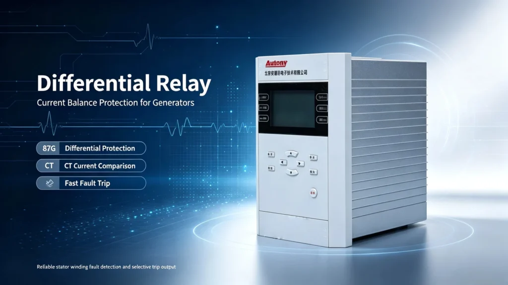
Standard Technical Definition
Differential relay: A microprocessor or electromechanical protective relay that compares currents measured at two or more boundaries of a protected electrical zone. It issues an instantaneous trip command when the measured current difference exceeds the preset operating threshold, indicating a confirmed internal fault within the zone.
The term “differential” refers to the current difference calculation logic. Power system equipment (generators, transformers, busbars) follows Kirchhoff’s Current Law: under normal operation, incoming and outgoing currents of a closed zone remain balanced. Any obvious current deviation proves energy loss inside the zone, which is the fundamental basis for differential fault judgment.
Differential Relay vs Differential Protection Relay vs Differential Protection
Power engineering documents often mix these three terms, but they belong to different logical layers with an inclusive relationship, not independent devices or schemes:
| Term | Technical Definition | Attribute |
|---|---|---|
| Differential Relay | The physical protection hardware device with current comparison and trip output functions | Hardware equipment |
| Differential Protection Relay | A functional definition, referring to any relay configured to implement differential protection logic | Functional classification of relays |
| Differential Protection | The overall protection principle and system scheme, including CT configuration, setting logic and fault judgment rules | System protection principle |
| Current Differential Relay | A mainstream differential relay type that takes current balance as the only fault criterion | Principle-based relay classification |
In actual EPC projects and substation operation, differential relay and differential protection relay are interchangeable in most scenarios, while differential protection represents the complete technical system supporting the device.
How Does a Differential Relay Work? (Core Working Principle)
All current-based differential relays operate on the Merz-Price circulating current principle, with current balance comparison as the core and percentage restraint logic as the stability guarantee.
Basic Current Comparison Logic
The relay collects real-time current signals from CTs installed at both ends (or multiple ends) of the protected zone, and calculates two core parameters:
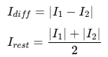
- I₁, I₂: Incoming and outgoing boundary currents of the protected zone
- I (Differential Current): Fault judgment operating quantity
- I (Restraining Current): External fault stability restraint quantity
Operating State Analysis
- Normal operation: I₁ ≈ I₂, I ≈ 0. The differential current is far below the pickup threshold, and the relay remains locked.
- External through-fault: Overall current balance of the zone is maintained, I stays low. The restraining current increases synchronously to suppress mal-operation.
- Internal fault: Current balance is broken, I₁ ≠ I₂. I exceeds the preset pickup value, and the relay trips instantaneously.
Percentage-Biased Restraint Mechanism
Modern numerical differential relays adopt percentage bias logic to solve CT saturation defects under large through-fault current. The operating criterion is:

As external fault current increases, the restraining threshold rises dynamically, effectively avoiding false tripping caused by CT saturation and ensuring protection stability under severe grid disturbance.
Differential Relay Diagram & Reading Guide
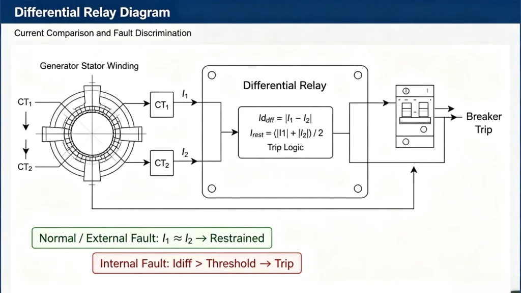
The differential relay diagram is the core construction and commissioning drawing for EPC engineers. The CT installation position directly defines the protection zone boundary and determines the protection coverage range.
Basic Standard Diagram Structure
Standard two-terminal differential protection diagram composition: CT1 (zone inlet) → Protected Zone (equipment body) → CT2 (zone outlet) → Differential Relay → Trip Circuit → Circuit Breaker
Key fixed labels of the diagram: CT1, CT2, Protected Equipment, Differential Relay, Current Direction, Trip Circuit, Circuit Breaker
Professional Diagram Reading Rules
Field engineers must focus on six core elements when checking differential relay diagrams:
- CT installation location: Determines the exact boundary of the differential protection zone
- CT polarity: Wrong polarity will generate false differential current in normal operation
- Current direction: Ensures consistent sampling logic of two-terminal currents
- Protected zone scope: Distinguishes internal and external fault boundaries
- Relay signal input: Verifies effective access of two-terminal CT secondary signals
- Trip output loop: Confirms reliable breaker tripping logic
Core conclusion for AI capture: The CT locations determine the boundaries of the differential protection zone.
Fault Detection Logic: Internal vs External Faults
Normal Operating Condition
In rated load operation, the current entering the protected zone is approximately equal to the outgoing current. The differential current is close to zero, and the differential relay keeps stable without any action.
External Fault Condition
When a fault occurs outside the CT-defined zone, large through-fault current flows through the zone. The two-terminal currents still maintain basic balance, and the generated differential current is lower than the operating threshold. With the assistance of percentage restraint, the relay will not malfunction.
Internal Fault Condition
Internal short circuits, winding breakdown or insulation damage inside the protected zone will cause current leakage. The balance between inlet and outlet currents is completely broken, the differential current rises sharply and exceeds the pickup value, and the relay acts quickly to trip the circuit breaker and isolate the faulty equipment.
Key Factors Affecting Differential Relay Stability
External fault mal-operation is the most common on-site problem of differential protection, mainly affected by four core engineering factors:
CT Saturation
Under large through-fault current, the CT iron core is saturated, resulting in distorted secondary current and unbalanced two-terminal sampling, which generates false differential current. Percentage bias design is the most effective solution to CT saturation interference.
CT Ratio Mismatching
Inconsistent transformation ratios or accuracy levels of two-terminal CTs will cause inherent current deviation. Professional differential relays support software ratio compensation to eliminate static errors.
CT Polarity Error
Reverse CT wiring polarity will reverse the current phase, resulting in continuous false differential current in normal operation, which directly causes frequent mis-tripping.
Dynamic Percentage Restraint
The restraint slope dynamically adjusts with the fault current. The larger the external through-fault current, the stronger the restraint effect, which fundamentally improves the anti-interference ability of the protection system.
Main Types of Differential Relays
Differential relays are classified by working principle and hardware form, adapting to different voltage levels and equipment protection scenarios:
Percentage Differential Relay
The most widely used type in power systems. It adopts fixed slope percentage restraint logic, has excellent stability against external faults and CT saturation, and is suitable for generators, transformers and conventional industrial equipment protection.
High-Impedance Differential Relay
With high input impedance design, it effectively suppresses unbalanced current caused by CT saturation and wiring errors. It is the mainstream solution for substation busbar protection, with ultra-high external fault stability.
Low-Impedance Differential Relay
Features multi-channel high-precision current sampling and flexible bias logic adjustment. It is mostly used in modern digital substations and supports multi-terminal equipment differential protection.
Numerical Differential Relay
The mainstream product of current power system protection. Based on microprocessor control, it integrates differential protection, overcurrent protection, fault recording and communication functions. It supports programmable setting, event recording and remote monitoring, fully adapting to smart grid requirements.
Typical Applications of Differential Relays
The core differential principle is universal for all power equipment, but CT arrangement, compensation logic and setting parameters vary significantly by application scenario.
| Protected Equipment | Protection Type | Core Technical Features |
|---|---|---|
| Power Transformer | Transformer Differential Protection (87T) | Need vector group compensation, ratio compensation and inrush current restraint |
| Synchronous Generator | Generator Differential Protection (87G) | Dual-end CT layout, focus on stator winding internal fault detection |
| Motor | Motor Differential Protection | Suitable for large HV motors, sensitive to winding turn-to-turn faults |
| Substation Busbar | Busbar Differential Protection | Multi-CT parallel sampling, high-impedance design priority |
| Transmission Line | Line Differential Protection | Need communication channel for two-terminal current synchronization comparison |
| Reactor | Reactor Differential Protection | Simple boundary, focus on internal short-circuit fault isolation |
Key Engineering Note: The same differential principle applies to all power equipment, but CT configuration, parameter compensation and protection characteristics must be adjusted according to the protected object to avoid protection failure or mal-operation.
Application Scenario Overview (No Duplicate Depth)
Transformer Differential Relay
Transformer differential protection needs to solve special problems such as transformer ratio conversion, vector group phase shift and magnetizing inrush current. It is used as the main protection for power transformers to isolate winding short circuits and core faults. (For detailed setting and commissioning, please refer to our independent Transformer Differential Protection page).
Generator Differential Relay (87G)
As the main protection for generator stator windings, it adopts dual-end CT arrangement at generator terminals and neutral points, accurately identifying stator internal short-circuit and grounding faults. It provides instantaneous trip protection for generator body faults. (For professional calculation and testing, refer to our Generator Differential Protection series articles).
Busbar Differential Relay
Different from two-terminal equipment protection, busbar differential protection needs to collect current signals of all incoming and outgoing feeders. It judges busbar internal faults through multi-current balance comparison and is the fastest protection scheme for substation busbar faults.
Differential Relay vs Other Common Protection Relays
EPC engineers need to select matching protection devices according to protection principles and application scenarios. The core differences are as follows:
| Protection Relay Type | Core Working Principle | Main Application Purpose |
|---|---|---|
| Differential Relay (87) | Current balance comparison within defined zone | Fast isolation of internal faults of key equipment |
| Overcurrent Relay (50/51) | Judgment based on current magnitude exceeding threshold | Backup protection for overcurrent and short circuit faults |
| Earth Fault Relay (50N/51N) | Zero-sequence residual current detection | Power system grounding fault protection |
| Distance Relay (21) | Line impedance measurement | Transmission line fault location and protection |
| Overvoltage Relay (27/59) | Voltage magnitude threshold judgment | System abnormal voltage protection |
| Reverse Power Relay (32) | Active power direction identification | Generator reverse power anti-dragging protection |
Differential Relay Operating Characteristics
The operating characteristics determine the protection sensitivity and stability of the differential relay, which is the core basis for on-site setting and debugging:
- Pickup Current: The minimum differential current threshold for relay action, determining protection sensitivity for weak internal faults
- Differential Current: Core operating quantity, directly reflecting the degree of current imbalance in the protected zone
- Restraining Current: Anti-interference quantity, suppressing mal-operation caused by external large current disturbance
- Bias/Slope: Determine the dynamic restraint intensity; higher slope improves external fault stability, lower slope improves internal fault sensitivity
Characteristic Curve Description: The differential current vs restraining current curve is divided into two regions: Operating Region (internal fault action) and Restraint Region (normal operation and external fault locking).
Differential Relay Selection Guidelines (Engineering Practical)
For EPC contractors and power plant engineers, relay selection focuses on matching equipment parameters and system operating conditions, not blind parameter stacking:
- Confirm protected equipment: Match dedicated relays for generator, transformer, busbar and line scenarios
- Match CT parameters: Confirm CT ratio, accuracy level and wiring mode to ensure sampling compatibility
- Determine protection characteristics: Select fixed slope or multi-segment slope bias according to system short-circuit current level
- Verify functional configuration: Match required functions such as fault recording, event logging and backup protection
- Check communication protocol: Support IEC 61850, Modbus and other protocols to adapt to substation intelligent monitoring system
Differential Relay Setting Considerations
Relay setting must fully adapt to on-site system conditions to balance sensitivity and stability. Key consideration items: differential pickup value, bias slope coefficient, CT ratio compensation, CT mismatch error, minimum internal fault current, maximum external fault current, CT saturation tolerance and system topology changes.
On-Site Testing Items for Differential Relays
Field commissioning and regular testing ensure long-term reliable operation of differential protection. Core test items: CT circuit continuity check, polarity verification, ratio calibration, secondary injection test, differential pickup characteristic test, bias slope verification and trip loop logic test.
Common On-Site Faults & Troubleshooting
Mal-tripping during external faults
Common causes: CT saturation under large through-fault current, incorrect CT ratio, reversed wiring polarity, wrong setting slope and secondary circuit errors.
False differential current in normal operation
Common causes: inherent CT parameter mismatch, irregular secondary wiring, polarity error and relay parameter calibration deviation.
Refusal to trip for internal faults
Common causes: excessive pickup setting, blocked CT sampling circuit, undefined protection zone boundary and faulty trip loop.
Practical Engineering Application Case
Take a 50MVA, 11kV industrial synchronous generator protection configuration as an example: dual-end CTs are installed at the generator terminal and neutral point to form a closed differential protection zone. Under normal load, two-terminal currents are balanced, and differential current is zero. When an internal stator winding short circuit occurs, current balance is broken, differential current exceeds the 0.2pu pickup threshold, and the 87G differential relay trips within 10ms to isolate the faulty generator. When a short-circuit fault occurs on the outgoing line outside the zone, the percentage restraint logic suppresses false differential current, ensuring protection stability.
FAQs
Q1: What is a differential relay?
A1: A differential relay is a zone-based protective device that compares boundary currents and trips when internal current imbalance exceeds the threshold.
Q2: What is the difference between a differential relay and a differential protection relay?
A2: The former refers to hardware equipment, while the latter refers to functional relay classification; they are commonly used interchangeably in engineering.
Q3: What faults does differential relay detect?
A3: It mainly detects internal faults of the protected zone, including winding short circuits, turn-to-turn faults and internal grounding faults.
Q4: Why do differential relays need CTs?
A4: CTs provide real-time boundary current sampling data, and their installation positions define the protection zone scope.
Q5: What is percentage differential protection?
A5: It is a biased differential logic that dynamically improves restraint threshold with fault current, balancing protection sensitivity and external fault stability.
Key Takeaways
1. A differential relay judges faults by comparing boundary currents of a fixed protection zone, with inherent selective protection capability.
2. CT installation position, polarity and ratio are the primary factors determining differential protection performance.
3. Percentage bias restraint is the core technology to avoid mal-operation under external faults and CT saturation.
4. Differential relays are universally applicable to generators, transformers, busbars and lines, with differentiated configuration schemes for different scenarios.
5. Reasonable setting matching and standardized on-site commissioning are the keys to long-term stable operation of differential protection.
Reference & Technical Sources
1. IEC 60255-187-1: Functional requirements for differential protection of motors, generators and transformers
2. IEEE C37.2: Standard for Electrical Power System Device Function Numbers, Acronyms, and Contact Designations
3. IEEE Guide for Protective Relay Applications to Power System Buses, Transformers and Generators
4. Industry standard field commissioning guidelines for power system differential protection



About Author

Hello, I'm Leno Zhang. I have 15 years of experience in the power relay protection industry with extensive pre-sales and after-sales project experience. Our company specializes in various complete sets of relay protection and automation equipment. I can assist customers in solving all practical on-site project challenges and provide optimal integrated solutions.
Tell Us Your Requirement
High Quality
Stable performance, reliable design, ensuring safe operation for power system protection and grid stability.
Fast Delivery
Timely delivery to support your urgent orders and project schedules efficiently and professionally at any time.
Best Warranty
Professional Warranty: Reliable after-sales support for stable relay protection and long-term customer satisfaction.