

-
Leon Zhang sales consultant
-
Email: zxl635973785@gmail.com
-
Phone/WhatsApp: +86 13655813266
What Is Reverse Power Flow Protection? Principle, ANSI 32 and Applications
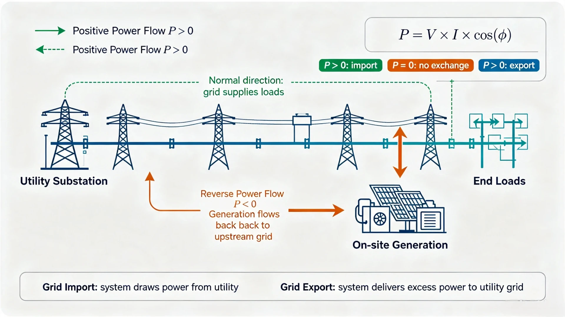
Reverse power flow protection is ANSI 32: a directional power element that watches the sign of active power at a machine terminal and acts when that sign flips. The relay reads P, holds any negative reading for a set delay, then alarms or opens the breaker. Nothing else on a generator panel does this job, because the fault itself is invisible to current-based elements.
At a glance
- Device number. ANSI 32, assigned by ANSI/IEEE C37.2-2008 rather than by any relay vendor.
- What it measures. Reverse power flow protection reads active power P, not current. A directional overcurrent element cannot catch this fault, because the current is ordinary load current.
- Trip logic. P below the pick-up value, held longer than the delay setting. Pick-up and delay are two separate settings and both matter.
- Typical pick-up. 2% to 8% of rated generator power on diesel units. Turbines run lower, 2% to 5%, because their transient window is shorter.
- Typical delay. 0.05 s to 300 s. The short end rides out switching transients; the long end waits for the prime mover to actually stop.
- Top cause of misfire. CT polarity reversed at commissioning. A reversed CT turns the whole direction logic upside down and the relay never sees the real condition.
- What it does not do. It is not anti-islanding and it is not export control. Those are separate functions sitting next to it in the same relay.
- Where it is applied. IEEE C37.102-2023 covers generator-side practice, IEEE 1547-2018 covers DER interconnection. Most sites are judged against both.
Where to Start, by Your Role
Three people touch the same ANSI 32 element on the same panel, and they should not start in the same place. This is the order we use when commissioning a site that has never had this function before.
- Protection engineer. Start with the CT polarity check, then the pick-up, then the delay. If the polarity is wrong, the other two numbers are decoration.
- EPC or design. Start by deciding where reverse power is measured: the generator breaker, the point of common coupling, or the HV side of the step-up transformer. That choice fixes how many CTs the panel needs.
- Plant owner. Start with the failure you have actually had. A generator that motored for twenty minutes is a different problem from a utility that rejected the commissioning spreadsheet.
- Commissioning tester. Start with the operating-time test at the smallest pick-up and walk up from there. That one sequence covers pick-up, delay and CT wiring at the same time.
ANSI 32 is a device number, not a standard. The number itself comes from ANSI/IEEE C37.2-2008, the list of electrical power system device function numbers. Generator-side practice sits in IEEE C37.102-2023, the Guide for AC Generator Protection. DER and solar interconnection sits in IEEE 1547-2018, with its test companion IEEE 1547.1-2020. The relay as a measuring device is judged against IEC 60255-1:2022. Older drawings and several vendor application notes still quote IEC 60255-118-1 for directional power. That part of the 60255 series is synchrophasor measurement. It has nothing to do with power direction, and quoting it here is a common error.
Common Causes of Reverse Power Flow
Reverse power is a symptom. The element trips, but the event that caused it happened somewhere else, usually upstream of the relay. The five triggers below account for nearly every case we have been called out to look at.
- Excessive solar generation. Midday PV output exceeds on-site load and the surplus reverses through the point of common coupling. Designed behaviour for an export-approved site, a fault for a zero-export site.
- Generator abnormal operation. Prime mover failure, a lost governor signal, or a parallel unit taking its share of bus load. Power comes in from the grid and the machine becomes a motor.
- Grid and microgrid switching. The transition between grid-tied and islanded inverts the power direction for a few seconds every time it happens.
- Wiring and measurement errors. Reversed CT polarity or a wrong phase sequence. The relay sees the wrong sign and can trip a perfectly healthy generator.
- Unplanned islanding. The utility line is de-energised for maintenance, local generation keeps feeding it, and the direction is now from the DER into the grid.
Diagnosis order is short. Check the direction of the CT wiring before you touch any setting number.
Is Reverse Power Flow Always a Problem?
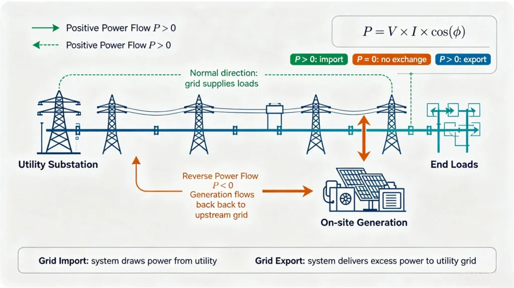
No. Power flowing out to the grid is what a grid-tied solar plant is paid to do, and a generator exporting to its own loads is normal. The distinction that matters is intentional against accidental, and the protection element only earns its place where the accidental case exists.
- Permissible reverse power flow. Designed export from a grid-tied solar or wind project, allowed by the interconnection agreement, metered at the point of common coupling.
- Hazardous reverse power flow. Unintentional reversal: generator motoring, backfeed into a dead utility line, or unwanted export on a zero-export site.
The harder case is the zero-export site. The utility contract forbids export and the site still has to prove it never happened. That is where the ANSI 32 element earns its keep. It detects a sustained negative P at the point where the contract says export is measured. It cannot police every millisecond. It only catches the condition that lasts.
Purpose of Reverse Power Protection
Three reasons, given here in the order they usually turn up in a fault report.
Prevent Generator Motoring Damage
Generator motoring is the severe one. When the prime mover fails, the machine does not simply stop generating. It keeps turning, driven by the grid, and consumes power like a synchronous motor. The current is small, a few percent of the rating, which is exactly why the unit survives long enough to do real damage before anything notices.
What that damage looks like depends on the machine. Diesel units take the worst of it: the crank is driven backwards through an engine trying to run forwards, and cylinder liners, pistons and the turbo go first. Steam and combustion turbines heat the blade path and the shaft. Either way the window is minutes, not seconds, and the protection has to act before the first one closes.
Protect Transformers and Upstream Grid Assets
Reverse power on the HV side of a unit transformer is a different event from motoring. A local source feeding into a section of network that is meant to be dead leaves the upstream protection blind. Viewed from the utility side it looks like load being energised by something with no fault current behind it.
The consequences are overvoltage on the de-energised section, circulating current through parallel paths, and the risk that upstream overcurrent and reclosing logic misreads the transient. A directional power element at the transformer HV terminal is the cheapest way to stop the backfeed before it starts.
Meet Solar and DER Grid Interconnection Standards
Interconnection rules for distributed generation expect the site to know what it is exporting and to stop when it should not be exporting. IEEE 1547-2018 sets the performance and the measurement accuracy the site interface has to meet, with active power within about 5% between 20% and 100% of rated. IEEE 1547.1-2020 is the conformance test that demonstrates it.
A single ANSI 32 element does not make a site compliant. What it does is give the site a measurable, testable answer to one question: was power going the wrong way, and for how long. The rest of the compliance case is voltage and frequency ride-through, anti-islanding and export limiting, all in the same relay.
Reverse Power Protection Working Principle
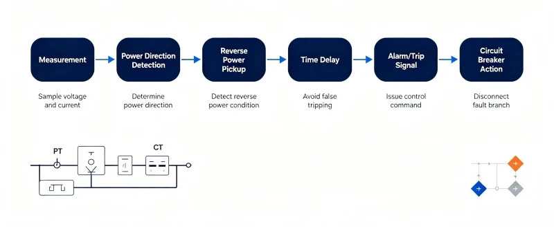
The reverse power protection principle is one measurement and one direction test. Nothing more. The element does not judge magnitude against a setting the way an overcurrent relay does. It judges the sign of the measured power against a threshold, then holds that result for a timer.
- Voltage and current signal acquisition. CT and PT or VT outputs feeding the relay.
- Power calculation. Three-phase active power from voltage, current and phase angle.
- Direction detection. Negative P flagged against the pick-up value.
- Pick-up and delay logic. Condition met, then held, then acted on.
- Output. Alarm contact, or breaker trip coil.
Voltage and Current Signal Acquisition
The sensing layer is conventional and unforgiving. Wrong inputs in, wrong trip out, no exception.
- CT (current transformer). Samples the load and generation current, one set per phase, oriented so the secondary current enters the relay from the correct side of the marking.
- PT or VT (voltage transformer). Samples system voltage. It has to come from the same bus the protecting device sits on, for a valid phase angle.
- Ratio configuration. The relay must know the CT and VT ratios before it can compare a measured secondary power against a primary-rated setting.
- Polarity. The single most common defect on this function, and it stays invisible until load is applied.
Accurate CT and VT ratio configuration and correct wiring polarity are prerequisites, not nice-to-haves. If either is wrong the element still reports a number. It just reports the wrong one.
Reverse Power Protection Calculation
The relay sums active power per phase and adds the three results.
P = Σ Vphase × Iphase × cos(φ), where φ is the angle between that phase voltage and that phase current.

P is positive when the machine delivers to the network and negative when the network delivers to the machine. That single sign is the whole basis of the element. Two things make it easy to get wrong.
- Sign convention. The relay has to be told which way is forward at this terminal. On a generator breaker that is usually out of the machine. At a point of common coupling it is out of the site. Get it backwards and the relay protects the healthy condition.
- Reactive power is not enough. Q flowing backwards on a lightly loaded line produces no negative P at all. A reverse power element will never see it, and a directional overcurrent element may see it but cannot tell you the machine is motoring.
In practice the number that triggers the trip is small. A 2 MW diesel unit drawn backwards as a motor may take 20 kW to 60 kW, well under 5% of rating and below the pick-up of most overcurrent settings. That is the point of the function.
ANSI 32 Reverse Power Protection Relay Logic
The logic is a pick-up contact in series with a timer. Both have to close.
- The power drops below the pick-up value and stays there.
- The timer runs for the set delay.
- At delay expiry the output contact changes: alarm, or trip.
- Below pick-up the timer resets, usually instantly, and the output returns.
Newer numeric relays add an alarm-versus-trip selection and, on some models, a block that suppresses the trip while the breaker is already open. Neither changes the physics. See the ANSI 32 reverse power protection relay for how those options are wired in practice.
Reverse Power Flow Protection for Solar PV Systems
Solar is where this function is specified most often, and where it is most often specified in the wrong place. The element belongs at the point of common coupling, not at the inverter.
Root Causes of Reverse Power in Solar Systems
A PV array produces when the sun is up and the plant load is not. That mismatch defines the whole problem. Midday generation runs ahead of site consumption, the surplus has nowhere to go but the grid, and the direction at the point of common coupling flips. Cloud cover and the evening ramp do the same thing in smaller steps.
On a zero-export site every one of those steps is a violation. The protection cannot prevent the reversal. It can only detect the sustained case and record it. Prevention belongs to the inverter export limit. Detection belongs to the ANSI 32 element at the point the contract measures.
Grid-Tied Solar Reverse Power Protection Scheme
A workable scheme has four parts.
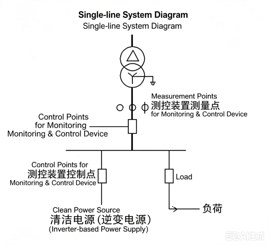
- Measurement at the point of common coupling. Metering CTs on the line side of the service transformer, rated for normal load current, not just the array current.
- A directional element in the relay. One ANSI 32 function tracking reverse power magnitude and duration at that same location.
- Inverter power limiting. The actual export cap. Without it the relay is the second line of defence, not the first.
- Records. Reverse power events logged with timestamp and magnitude, which is what an interconnection agreement usually asks for.
For a low-voltage site where the whole array sits behind one service transformer, see the low-voltage PV reverse power protection case for the wiring and setting sequence that passed commissioning.
Reverse Power Protection for Diesel Generator Systems
On diesel plants the question is narrower. How long before the engine is damaged, and which breaker opens first?
Generator Reverse Power and Motoring Risks
Parallel diesel units make this worse. When one unit loses its governor and another takes the bus load, the faulted machine is dragged by the bus instead of by its own engine. Fuel interruption, a failed start attempt and a desynchronised close all produce the same condition.
Sustained motoring heats the cylinders, shakes the block and wears the prime mover permanently. The machine keeps turning and keeps absorbing power the whole time, which is why the trip has to come from a power direction element and not from an operator noticing that something sounds wrong.
ANSI 32 Protection Mechanism for Generators
The relay samples generator active power continuously. When sustained reverse power above the pick-up is detected it trips the generator breaker and isolates the unit. The rest of the bus keeps running on its healthy units, and that isolation is the design intent rather than a side effect.
Coordination is tighter here than on a sole-unit plant. The delay has to be longer than the transient produced by closing into a loaded bus, and shorter than the time it takes crankshaft damage to become permanent. Generator-side practice, including the pick-up table by machine class, is set out in generator reverse power protection.
Reverse Power Protection in Microgrids and Hybrid Power Systems
A hybrid plant has no steady power direction. Solar comes and goes, the battery charges in one state and discharges in the next, and the diesel may or may not be running. Sorting intentional reversal from unintentional one is a settings problem here, more than a hardware problem.
Solar + Diesel Hybrid Systems
In sunshine the array supplies the loads first. Whatever is left goes into an idle diesel set or out to the grid. A diesel standing idle and absorbing power is the classic reverse power event in this topology, and it is easy to miss because nothing has failed.
BESS + Solar Microgrids
Batteries switch direction constantly by design. A fast charge and discharge cycle inverts power repeatedly within seconds, so the delay setting on this element is doing real work. It has to be long enough that a battery changing direction is not reported as a fault, and short enough that a genuine backfeed still trips.
The delay is the whole answer here.
Grid-Tied and Islanded Mode Switching
Mode transfer is the highest-risk window in the whole plant. The instant the tie breaker opens, the direction at every downstream meter inverts, and the plant redefines what forward means. The element has to ride through the transition and act only on what happens after it.
Reverse Power Protection Relay Settings
Critical Note: reverse power flow protection has no universal setting. Every value below is a starting point taken from the generator rating, not a specification. Pick-up, delay and CT binding all have to be re-derived for the site, and the utility interconnection agreement normally overrides the vendor default. No universal fixed value applies to all projects.
Reverse Power Pickup Setting
Set the pick-up as a percentage of rated generator power and leave room on both sides. Too high and the element never sees the motoring case. Too low and the transient during load rejection trips a healthy unit.
A reverse power flow protection pick-up of 2% to 8% of rated power is the usual band for diesel engines. Turbine-generators sit lower, at 2% to 5%, because their transient window is shorter and the machine cannot absorb a mis-trip. Both bands assume the relay is measuring at the machine terminals with the correct CT polarity. Shift the pick-up by a point or two afterwards if site testing shows nuisance operation.
Time Delay Setting
Start long, then cut it if a switching transient trips the unit.
The delay window runs from 0.05 s to 300 s and does double duty. At the short end it ignores the few-hundred-millisecond reversal produced by load switching or a solar ramp. At the long end it waits for the prime mover to genuinely stop producing, which is the only condition worth tripping on.
Set it against the rest of the protection stack. The reverse power element should act after overcurrent and after any under-frequency load shedding, and before the upstream backup trip. If your delay is shorter than the inverter anti-islanding response, the two are fighting.
CT Ratio and Polarity Calibration
Wrong CT polarity is the leading cause of reverse power protection misoperation, and it turns up at commissioning far more often than at design. Verify CT installation direction, phase sequence and ratio matching on site before trusting any setting.
Protection Coordination with Other Functions
A directional power element on its own leaves gaps. Coordinate it with overcurrent, over and under voltage, over and under frequency, and anti-islanding protection, so the plant has no window where reverse power is neither measured nor tripped.
Reverse Power Protection Wiring Diagram
Reverse power flow protection wiring is standard. It does not change between a 2 MW diesel set and a 2 MW solar plant.
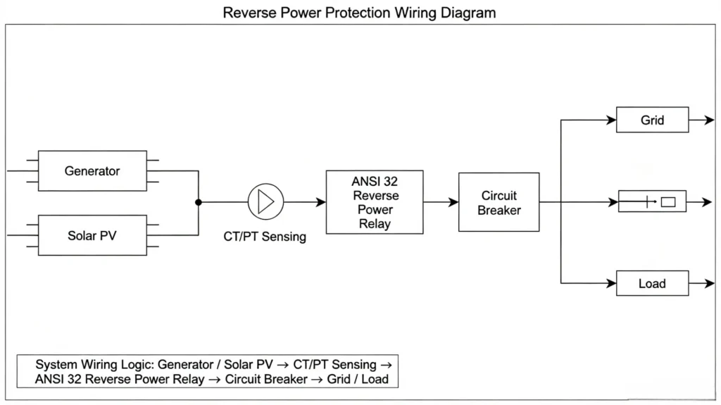
System Wiring Logic
Signal path, in order:
Generator or PV output → CT and PT sensing → ANSI 32 reverse power relay → output contact → circuit breaker trip coil → grid or load.
The relay needs voltage from the same bus it is protecting. A missing VT feed is a common commissioning miss. The current side reads fine, the power calculation reads zero, and the element never picks up.
The VT feed is the one that gets overlooked.
Core Wiring Verification Points
- Three-phase CT polarity and current direction consistency
- Correct phase sequence of the voltage and current signals
- Independent DC supply and control loop for the relay
- Reliable trip circuit connection between the relay output and the breaker trip coil
- VT secondary earth and anti-feeder-short circuiting in place
How to Test ANSI 32 Reverse Power Protection
Commissioning and maintenance testing of this function follows the same three steps every time. ANSI 32 testing is cheap inside the commissioning window and expensive six months later as a waking-up-the-pl



About Author

Hello, I'm Leno Zhang. I have 15 years of experience in the power relay protection industry with extensive pre-sales and after-sales project experience. Our company specializes in various complete sets of relay protection and automation equipment. I can assist customers in solving all practical on-site project challenges and provide optimal integrated solutions.
Tell Us Your Requirement
High Quality
Stable performance, reliable design, ensuring safe operation for power system protection and grid stability.
Fast Delivery
Timely delivery to support your urgent orders and project schedules efficiently and professionally at any time.
Best Warranty
Professional Warranty: Reliable after-sales support for stable relay protection and long-term customer satisfaction.