-
Leon Zhang sales consultant
-
Email: zxl635973785@gmail.com
-
Phone/WhatsApp: +86 13655813266


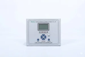
Low Voltage ATS Controller | ASZ-526H Automatic Transfer Switch Device
ASZ-526H Low Voltage ATS Controller is developed for automatic control of low-voltage multi-power supply. It supports standby power switching, closed-loop operation and dual/multi-power transfer, applicable to 2-incoming, 2-incoming-with-bus-coupler and 3-incoming wiring schemes.
Communication Mode:Optional: RS-485, CAN bus, IEC 61850 , IEC 60870-5-103
In-house Factory & Technical Team, OEM ODM Custom Electrical Equipment
Send your requirements, we will quote for you within 12 hours
Description
Overview of Low Voltage ATS Controller
- ASZ-526H Low Voltage ATS Controller is developed for automatic control of low-voltage multi-power supply. It supports standby power switching, closed-loop operation and dual/multi-power transfer, applicable to 2-incoming, 2-incoming-with-bus-coupler and 3-incoming wiring schemes.
- Low Voltage ATS Controller is applicable to power distribution systems with dual power supply for critical loads in industry, medical care, finance, data centers, government offices, post & telecommunications, coal, metallurgy, railway, marine, military facilities and expressways.
Model Description: LV Automatic Transfer Switch Relay
| Model | Control Mode | Application Mode | Remark |
|---|---|---|---|
| ASZ-526H-A20 | Dual power automatic transfer controller | Mains-Mains, Mains-Generator, Auto/Manual | |
| ASZ-526H-B20 | Dual power automatic transfer controller (with closed-loop parallel function) | Mains-Mains, Mains-Generator, Auto/Manual | |
| ASZ-526H-A21 | Dual power bus coupler automatic transfer controller | Mains-Mains-Bus Coupler, Auto/Manual | |
| ASZ-526H-B21 | Dual power bus coupler automatic transfer controller (with closed-loop parallel function) | Mains-Mains-Bus Coupler, Auto/Manual | |
| ASZ-526H-A30 | Three-power automatic transfer controller | Mains-Mains-Mains, Mains-Mains-Generator, Auto/Manual | |
| ASZ-526H-B30 | Three-power automatic transfer controller (with closed-loop parallel function) | Mains-Mains-Mains, Mains-Mains-Generator, Auto/Manual |
Features of Closed-Transition ATS Controller
- Equipped with overvoltage, undervoltage, phase loss, reverse phase sequence, overcurrent, overfrequency and underfrequency protection.
- Real-time clock display and historical data storage, circularly recording up to 500 entries.
- Compatible with 3-phase 4-wire and 3-phase 3-wire AC power systems.
- Controls closing and tripping of two incoming breakers and bus coupler breaker simultaneously to simplify control system.
- Delays closing operation till PF ready signal is received for stored-energy breakers.
- Auto/manual mode switch, manual breaker operation available under manual mode.
- Six physical switch transfer buttons on panel for convenient manual control.
- Reclosing function with enable/disable option.
- Closing output supports pulse or continuous signal mode.
- On-site programmable parameters with password protection against unauthorized operation.
- Isolated design for two neutral lines.
- LO/NO power output supplies power for breaker switching coils.
- Widely spaced AC terminals, maximum withstand voltage up to 625V AC.
- Built-in communication port adopting ModBus protocol, realizing remote control, signaling, measurement and parameter adjustment. Supports remote start/stop of generator sets and remote ATS switching.
General Technical Parameters of Low Voltage ATS Controller
Ambient Conditions
Normal Operating Atmospheric Conditions
- a. Ambient temperature: -25℃ ~ +70℃
-
b. Relative humidity: 5% ~ 95%, no condensation or icing inside the device
-
c. Atmospheric pressure: 80kPa ~ 106kPa
Normal Test Atmospheric Conditions
- a. Ambient temperature: +15℃ ~ +35℃
-
b. Relative humidity: 45% ~ 75%
-
c. Atmospheric pressure: 80kPa ~ 106kPa
Reference Test Atmospheric Conditions
- Unless specified otherwise, ambient conditions for inherent accuracy verification:
-
a. Ambient temperature: (20±5)℃
-
b. Relative humidity: 45% ~ 75%
-
c. Atmospheric pressure: 86kPa ~ 106kPa
Storage and Transportation Conditions
- a. Transportation temperature: -40℃ ~ +70℃, relative humidity ≤85%. No irreversible changes under unpowered state.
-
b. Storage temperature: -25℃ ~ +55℃, relative humidity ≤85%.
Surrounding Environment
- a. No explosion hazards, corrosive gas, conductive dust, severe mildew and violent vibration sources.
-
b. Equipped with protection against rain, snow, wind, sand, dust and static electricity.
-
c. Comply with Class B safety requirements of GB/T 9361-2011; grounding resistance meets Clause 5.8 of GB/T 2887-2011.
Electrical Parameters
Rated Ratings
| Item | Parameter |
|---|---|
| Operating Voltage | AC 85-480V (80%~120% fluctuation); DC 110V/220V |
| Remote Signal Voltage | DC 24V |
| AC Voltage Input | 3-phase 4-wire / 3-phase 3-wire, Max 690V AC, PT ratio adjustable |
| AC Current Input | 5A (0.05~6A), CT ratio adjustable |
| Rated Frequency | 50Hz |
Power Consumption
- AC voltage circuit: <0.5VA per phase
-
AC current circuit: <0.75VA per phase
-
Total power consumption: ≤15VA
Overload Capacity
- AC voltage: Continuous operation at 1.2 times rated voltage
-
AC current: Continuous operation at 1.2 times rated current
Main Technical Specifications
| Item | Parameter |
|---|---|
| Remote Signaling | 12 input channels; Opto-isolated passive contact, 1500VDC isolation voltage; Internal DC24V excitation, NO/NC contact configurable; Signal resolution ≤2ms |
| Remote Control Output | 6 channels: 16A, AC250V passive output; 6 channels: 8A, AC250V passive output |
| Communication Interfaces | 1×10/100Base-TX Ethernet port; 2×RS485 interfaces |
| Reliability | MTBF ≥50000 hours |
| Insulation Performance | Insulation resistance ≥5MΩ (between circuits & ground, among separate circuits); Withstand 50Hz 2.0kV AC voltage test for 1min without breakdown/flashover; Withstand 5kV standard lightning impulse voltage between circuits & ground |
FAQ
Q: What is Make-Before-Break ATS Relay?
A: It is a switching relay that closes the standby power circuit before disconnecting the main power, realizing transient parallel connection to avoid instantaneous power outage during transfer.
Q: Definition of No-Break Automatic Transfer Switch
A: It refers to non-interruptible power transfer switch, which maintains continuous power supply to loads throughout power switching process without power cut.
Q: What does ABTD stand for?
A: ABTD is short for Automatic Bus Transfer Device, an automatic controller used for intelligent switching and interconnection of busbar power supply.
Q: Core difference between Make-Before-Break and No-Break ATS
A: Make-Before-Break adopts brief overlapping switching; No-Break ATS achieves zero power interruption for load power supply during conversion.
Q: Application scenarios of Automatic Bus Transfer Device
A: Widely used in dual or multi-busbar power distribution systems for automatic bus coupling, power switching and isolated grid power regulation.
2 reviews for Low Voltage ATS Controller | ASZ-526H Automatic Transfer Switch Device
Related products


High Quality
Stable performance, reliable design, ensuring safe operation for power system protection and grid stability.
Fast Delivery
Timely delivery to support your urgent orders and project schedules efficiently and professionally at any time.
Best Warranty
Professional Warranty: Reliable after-sales support for stable relay protection and long-term customer satisfaction.
xiao zhang –
Low-voltage ATS device features reliable logic and rapid automatic switching, ensuring uninterrupted power supply when main feeder fails, widely applied in 400V distribution cabinets of substations.
Jack –
Compact size saves panel space without compromising performance.