

-
Leon Zhang sales consultant
-
Email: zxl635973785@gmail.com
-
Phone/WhatsApp: +86 13655813266
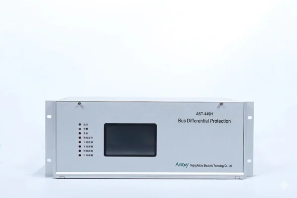
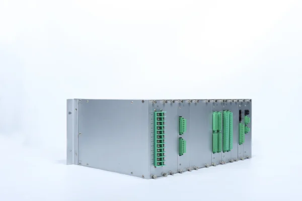
87B Relay | Bus Differential Protection Relay
Bus Differential Protection Overview
The bus protection with differential relay device is suitable for busbars in conventional substations rated at 110 kV and below regardless of wiring configuration; it supports up to nine connected units including the bus tie, perfectly fitting application scenarios of conventional substations.
Communication Mode:Optional: RS-485, CAN bus, Ethernet, IEC61850,IEC103
Send your requirements, we will quote for you within 12 hours
Description
Bus Differential Protection Relay Overview
- The bus protection with differential relay device is suitable for busbars in conventional substations rated at 110 kV and below regardless of wiring configuration; it supports up to nine connected units including the bus tie, perfectly fitting application scenarios of conventional substations.
- Busbar protection devices feature multiple protection functions and adopt flexible 87B bus differential protection schemes configurable to match various busbar wiring requirements.
What is an 87B Relay?
87B relay is a digital protection device that detects internal bus faults by comparing the vector sum of all currents entering and leaving the busbar. Under normal operating conditions, the current entering the bus equals the current leaving it (differential current ≈ 0). When an internal bus fault occurs, the current balance is disrupted, generating a differential current. The relay operates rapidly, tripping all connected breakers to isolate the faulty busbar.
Key Features of the 87B Protection Relay
Core Protection Functions
ANSI 87B Differential Protection – Based on Kirchhoff’s current law, compares incoming and outgoing currents to detect internal bus faults. Operating time: <20ms.
High-Speed Bus Fault Clearing – Differential protection operates within 20ms at 1.5× setting value. Combined with GOOSE communication (≤3ms) for ultra-fast fault isolation.
Check Zone Protection – Provides supervisory check over main differential zones to prevent mal-operation during external faults and minimize outage scope.
CT Broken-Line Detection – Built-in CT circuit monitoring. Employs weighted algorithms and dynamic recall techniques to effectively prevent mal-operation during CT saturation.
Circuit Breaker Failure Protection – Two-stage scheme: Stage 1 retrips the local breaker; Stage 2 issues remote trip via GOOSE.
Bus Tie Protection – Supports protection for bus tie/section breakers, adapting to various configurations such as double-bus with bus tie for load transfer scenarios.
Multiple Busbar Configurations – Adapts to single bus, double bus, breaker-and-a-half, ring bus, 3/2 breaker, and other main wiring schemes.
Communication Capabilities
IEC 61850 – Supports GOOSE (≤3ms), MMS, and Sampled Values (SV). Compliant with Edition 2.0.
Ethernet – Multi-port (RJ-45/fiber optic), supports VLAN segregation and QoS priority management for redundant communication architectures.
RS-485 – Supports legacy protocols including DNP3.0, Modbus RTU, and IEC 60870-5-103 for compatibility with existing substation equipment.
CAN & Other Interfaces – Up to 80 analog inputs, 192 binary inputs, and 117 trip outputs. Supports multiple protocols and interfaces for both new and retrofit projects.
87B Relay Technical Specifications
| Parameter | Specification |
|---|---|
| Protection Function | Bus Differential Protection |
| ANSI Code | 87B |
| Rated Voltage | ≤110 kV |
| Communication | IEC 61850 / IEC 103 / Modbus / Ethernet |
| Communication Ports | RS-485 / CAN / Ethernet |
| Protection Time | ≤25 ms |
| Bus Configuration | Single Bus / Double Bus |
| CT Supervision | Yes |
| Breaker Failure Protection | Yes |
87B Relay Applications
| Category | Applications |
|---|---|
| Voltage Levels | 110 kV substations, Medium-voltage substations |
| Busbar Configurations | Single busbar, Double busbar, Sectionalized busbar |
| Industry Sectors | Industrial substations, Power plants, Renewable energy substations |
Busbar Differential Protection Scheme
Protection startup criteria
- This current differential protection relay is equipped with two trip functions to adapt to power systems of different capacities and various fault types: fast trip based on differential current variation and delayed trip based on differential current integration. The fast trip enables rapid and precise fault detection, while the delayed trip guarantees reliable operating sensitivity.
Subfunctions of Differential Protection for 87B Differential Protection Relay
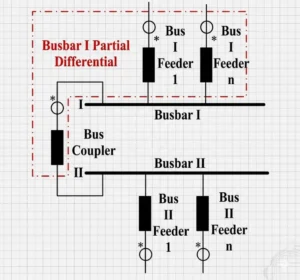
- Section I Busbar Ratio Restrained Minor Differential Protection Function
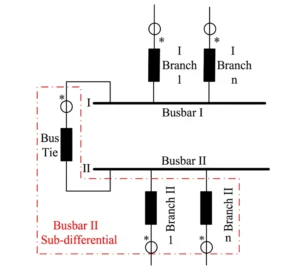
- Section II Busbar Ratio Restrained Minor Differential Protection Function
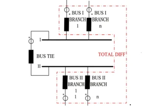
- Ratio Restrained Major Differential Protection Function
- CT Broken Line Blocking and Alarm Function
- Composite Voltage Blocking Function
Small-difference differential protection for Section I busbars
Section II Busbar Ratio Differential Protection Function
Ratio-based differential protection function
87B Relay Settings
| Category | No. | Name | Range | Unit / Definition |
|---|---|---|---|---|
| Differential Protection | 1 | Differential Protection Starting Current Setting | 0.25~100 | A |
| 2 | CT Broken Line Alarm Setting | 0.25~100 | A | |
| 3 | CT Broken Line Blocking Setting | 0.25~100 | A | |
| 4 | Bus Tie & Section Breaker Failure Current Setting | 0.25~100 | A | |
| 5 | Bus Tie & Section Breaker Failure Time Delay | 0~10 | s | |
| Breaker Failure Protection | 6 | Undervoltage Blocking Setting | 0~57.7 | V |
| 7 | Zero-sequence Voltage Blocking Setting | 0~57.7 | V | |
| 8 | Negative-sequence Voltage Blocking Setting | 0~57.7 | V | |
| 9 | Three-phase Failure Phase Current Setting | 0.25~100 | A | |
| 10 | Breaker Failure Zero-sequence Current Setting | 0.25~100 | A | |
| 11 | Breaker Failure Negative-sequence Current Setting | 0.25~100 | A | |
| 12 | Breaker Failure 1st Time Limit | 0~10 | s | |
| 13 | Breaker Failure 2nd Time Limit | 0~10 | s | |
| Optional Function
Bus Tie Charging Overcurrent Protection |
14 | Charging Overcurrent Stage I Current Setting | 0.25~100 | A |
| 15 | Charging Overcurrent Stage I Time Delay | 0.1~10 | s | |
| 16 | Charging Overcurrent Stage II Current Setting | 0.25~100 | A | |
| 17 | Charging Zero-sequence Overcurrent Setting | 0.25~100 | A | |
| 18 | Charging Overcurrent Stage II Time Delay | 0.1~10 | s |
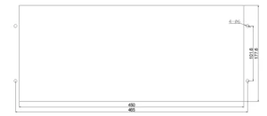
Appearance of a Busbar Differential Protection Device
Contact
For more information on the 87B Bus Differential Protection Relay, including customized configurations and technical support, please contact our sales team.
87B Relay – Frequently Asked Questions
Q1: What is the 87B relay?
The 87B relay is a bus differential protection relay designed for high-speed fault detection and isolation on busbars. It operates on the ANSI 87B function code and provides reliable protection for single bus, double bus, and sectionalized busbar configurations.
Q2: What is the typical operating time of the 87B protection relay?
The 87B protection relay adopts an instantaneous differential current algorithm, ensuring total operating time within 25ms. This fast response minimizes equipment damage and maintains system stability during bus faults.
Q3: Does the 87B bus differential protection relay support IEC 61850?
Yes. The 87B bus differential protection relay is equipped with 3 Ethernet ports and fully supports IEC 61850-MMS for monitoring system communication, as well as GOOSE messaging for high-speed peer-to-peer tripping.
Q4: What busbar configurations does the 87B relay support?
The 87B relay supports multiple busbar configurations including:
-
Single busbar
-
Double busbar
-
Sectionalized busbar
-
Double busbar with bus tie
-
Breaker-and-a-half and ring bus arrangements
Q5: Does the busbar differential protection relay require deactivation during bus switching operations?
No. The busbar differential protection relay automatically detects isolator switch position changes and adapts its differential calculation logic accordingly. No manual deactivation is needed during switching operations in double-bus configurations.
Q6: What communication ports are available on the 87B protection relay?
The 87B protection relay offers:
-
3 Ethernet ports (IEC 61850-MMS, GOOSE)
-
RS-485 (Modbus RTU, DNP3.0, IEC 60870-5-103)
-
CAN interface
Q7: Does the 87B relay include CT supervision?
Yes. The 87B relay features built-in CT broken-line detection to monitor current transformer circuit continuity, preventing mal-operation caused by open CT circuits.
Q8: Does the 87B bus differential protection relay include breaker failure protection?
Yes. The 87B bus differential protection relay integrates two-stage breaker failure protection (50BF) to provide backup clearing in case the primary breaker fails to open.
Q9: What time synchronization methods does the 87B relay support?
The 87B relay supports multiple time synchronization methods including SNTP, IRIG-B (Code B), and GPS pulse, ensuring accurate time-stamping for event recording and fault analysis.
Q10: What is the difference between large-difference and small-difference functions in the 87B relay?
In the 87B bus differential protection relay, the large-difference function protects the entire double-bus system as a single unit to detect internal faults, while small-difference functions protect each individual bus section to accurately locate the faulty section, minimizing outage scope.
Q11: Where is the 87B protection relay typically applied?
The 87B protection relay is widely used in:
-
110 kV substations
-
Medium-voltage substations
-
Industrial power systems
-
Power plants
-
Renewable energy substations (solar, wind)
Q12: Is the 87B bus differential protection relay suitable for retrofit projects?
Yes. With its multiple legacy protocol support (Modbus RTU, DNP3.0, IEC 60870-5-103) and flexible hardware interfaces, the 87B relay integrates seamlessly into both new installations and existing substation upgrades.
Recommended Products
2 reviews for 87B Relay | Bus Differential Protection Relay
Related products

High Quality
Stable performance, reliable design, ensuring safe operation for power system protection and grid stability.
Fast Delivery
Timely delivery to support your urgent orders and project schedules efficiently and professionally at any time.
Best Warranty
Professional Warranty: Reliable after-sales support for stable relay protection and long-term customer satisfaction.
xiao zhang –
Dependable bus differential protection (ANSI 87B). Quick fault tripping, strong anti‑CT‑saturation performance, suits various substation busbar configurations for global projects.
Jack –
Fast fault clearing time, enhances overall system stability.