

-
Leon Zhang sales consultant
-
Email: zxl635973785@gmail.com
-
Phone/WhatsApp: +86 13655813266
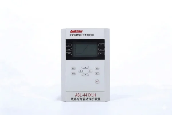
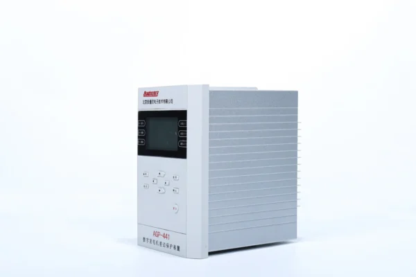
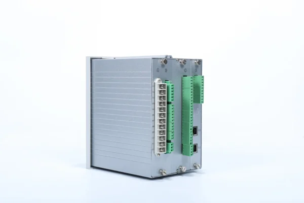
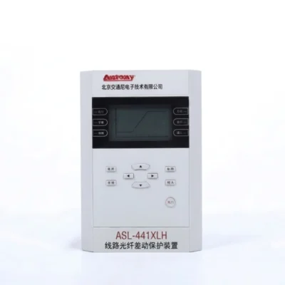
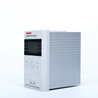
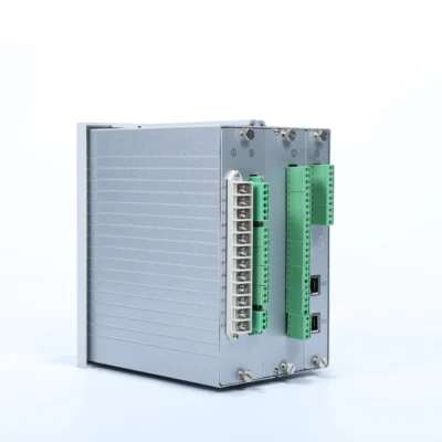
ASL-441XLH 87L Protection Relay
ASL-441XLH 87L Protection Relay
Multifunction numerical protection for high-voltage transmission lines
Key Protection Functions
- ANSI 87L fiber-optic line differential protection
- Directional overcurrent protection
- Zero-sequence directional overcurrent protection
- Auto-reclosing with synchronism check
- Underfrequency islanding protection
- Overvoltage and undervoltage protection
- VT disconnection monitoring
- Fault recording and event logging
Communication
Ethernet · RS485 · IEC 61850 · IEC 60870-5-103 · IRIG-B
Send your requirements, we will quote for you within 12 hours
Description
The ASL-441XLH is a multifunction numerical 87L protection relay designed for fast and selective protection of high-voltage transmission lines. Its primary protection function is fiber-optic line differential protection, which compares current information from both ends of the protected line to identify internal faults.
In addition to ANSI 87L, the relay integrates directional overcurrent, zero-sequence protection, auto-reclosing, voltage and frequency protection, VT disconnection monitoring and event/fault recording.
This combination allows the ASL-441XLH to provide primary 87L line differential protection together with backup and auxiliary protection functions in a single device.
ANSI 87L Line Differential Protection
What is ANSI 87L?
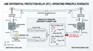
ANSI 87L is the IEEE/ANSI device number for Line Current Differential Protection. It is a high-speed, unit protection scheme that provides primary protection for transmission lines. Based on Kirchhoff’s Current Law, it compares currents at all line terminals to determine if a fault lies within the protected zone.
How does 87L Work?
87L relays exchange synchronized current phasors via high-speed communication channels (fiber optics, microwave, or pilot wires). The relay continuously calculates:
-
Differential current (I<sub>d</sub>) – vector sum of all terminal currents.
-
Restraint current (I<sub>r</sub>) – stabilizing quantity to prevent maloperation.
A trip is issued when the differential current exceeds the restraint characteristic — ensuring instantaneous operation for internal faults and stability for external faults.
Protected Zone
The protected zone is strictly defined as the line section between the CTs at all terminals.
-
100% line coverage with no under-reach or over-reach.
-
Instantaneous tripping (typically 1–2.5 cycles) for any fault within the zone.
Internal Fault
A fault within the protected zone.
Response: Fault current flows into the line from all terminals → high differential current → instantaneous trip at all terminals.
External Fault
A fault outside the protected zone.
Response: Fault current flows through the line (enters one side, leaves the other) → differential current near zero → relay remains stable (no trip).
Communication Between Line Terminals
| Requirement | Description |
|---|---|
| Channel | Fiber optic (primary), microwave, or pilot wire |
| Synchronization | GPS or IEEE 1588 for accurate phase alignment |
| Data | Current phasors, status, channel health |
| Latency | < 5 ms typical |
| Redundancy | Dual channels recommended for critical lines |
Trip decisions are made independently at each terminal using the same calculated differential and restraint current
87L Protection Relay working principle
- As a line differential protective relay, fiber-optic differential current protection operates on the principle of phase current differentials, and it mainly provides protection for phase-to-phase faults within the protected area as well as single-phase metallic ground faults in low-resistance grounding systems. Operating equation:
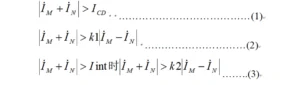
- Equation (2) is the main criterion, where M and N represent the two sides of the circuit.
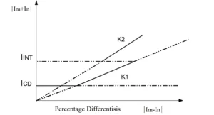
Designed for overhead and transmission line protection, this relay adopts two proportional restraint coefficients: K1 = 0.5 and K2 = 0.7.
- ICD: Minimum operate current, i.e. the pickup setting of differential current.
- IINT: Inflection point current, fixed at 4× rated current.
Differential Overload Alarm
A differential overload alarm will activate with a 2s delay once the measured differential current exceeds 0.5 times ICD.
CT Broken Circuit Blocking
The relay supports CT disconnection blocking logic. Phase-wise CT disconnection is confirmed only when both conditions below are met simultaneously:
- Differential current > 0.5 × ICD
- No current detected at the local terminal, while remote terminal current < 6 A
2nd Harmonic Restraint
The differential protection is blocked if the second harmonic component accounts for more than 20% of the fundamental current.
How to Set an ANSI 87L Protection Relay?
No universal setting exists — each application requires case-by-case evaluation.
| Factor | Key Consideration |
|---|---|
| 1. CT Ratio | Select ratios to avoid saturation; match both terminals where possible. |
| 2. Differential Pickup | Set above steady-state errors . Typical: 0.1–0.3 × I<sub>rated</sub>. |
| 3. Restraint Characteristic | Choose average or sum method per relay model. |
| 4. Slope Coefficients | K1: 0.2–0.5 (sensitivity); K2: 0.5–0.8 (stability). Breakpoint: 2–4 × I<sub>rated</sub>. |
| 5. Communication Delay | Measure and compensate for channel latency. Fiber: < 1 ms; others: 2–5 ms. |
| 6. CT Mismatch | Apply ratio correction or margin (1.05–1.15). |
| 7. Fault Current | Use short-circuit study for min (sensitivity) and max (stability/saturation) values. |
Final settings must be calculated according to the protected line parameters, CT characteristics, system grounding method, and the project protection coordination study.
Function of 87L Protection Relay
| Category | Function Description | ANSI Code |
|---|---|---|
| Protection Function | Fiber Current Differential Protection | 87L |
| Protection Function | Two-stage Low-voltage Blocked Interphase Directional Overcurrent Protection | 67/51 |
| Protection Function | Inverse-time Interphase Directional Overcurrent (Normal / Very / Extreme) | 67/51 |
| Protection Function | Three-stage Zero-sequence Directional Overcurrent Protection | 67N/51N |
| Protection Function | Inverse-time Zero-sequence Directional Overcurrent (Normal / Very / Extreme) | 51N |
| Protection Function | Three-phase Single-shot Auto-reclosing (Non-synchronism / Synchronism Check / Dead Voltage Check) | 79 |
| Protection Function | Acceleration Protection (Front Acceleration / Rear Acceleration) | 50/79 |
| Protection Function | Overload Protection | 51 |
| Protection Function | Under-frequency Islanding Protection | 81U |
| Protection Function | Overvoltage Protection | 59 |
| Protection Function | Undervoltage Protection | 27 |
| Protection Function | Voltage Transformer Disconnection Monitoring | 60 |
| Protection Function | Control Circuit Disconnection Monitoring | — |
| Data Acquisition | Current, Voltage, Active Power, Reactive Power, Power Factor, Frequency | — |
| Data Acquisition | 13-channel Remote Signals | — |
| Event Record | Protection Event Record | — |
| Event Record | Alarm Event Record | — |
| Event Record | Fault Wave Recording | — |
| Event Record | Remote Signal Change Event | — |
| Event Record | Operation Record Event | — |
| Control | Local / Remote Trip and Close Operation | — |
| Control | Remote Setting Modification | — |
| Control | Remote Protection Enable / Disable | — |
| Operation Box | Trip Position and Close Position Indication | — |
| Operation Box | Self-holding and Anti-jump Function | — |
| Operation Box | Trip / Close Current Adaptation | — |
| Operation Box | Control Circuit Disconnection Alarm | — |
| Communication | Ethernet (Recommended) | — |
| Communication | RS485 | — |
| Others | IRIG-B(DC) (Optional), IEC61850 (Optional) | — |
87L Protection Relay setting
| No. | Setting Name | Range | Unit | Remark |
|---|---|---|---|---|
| 1 | Control Word 1 | 0000~FFFF | — | Refer to control word description |
| 2 | Control Word 2 | 0000~FFFF | — | Refer to control word description |
| 3 | CT Ratio Compensation Coefficient | 0.025~40 | — | Compensate inconsistent TA ratios on both sides |
| 4 | Differential Current Setting | 0.2~40.0 | A | |
| 5 | Stage II Current Setting | 0.2~100.0 | A | |
| 6 | Stage III Current Setting | 0.2~100.0 | A | |
| 7 | Stage I Current Time Delay | 0.0~5.00 | S | |
| 8 | Stage II Current Time Delay | 0.1~20.00 | S | |
| 9 | Stage III Current Time Delay | 0.1~20.00 | S | |
| 10 | Stage I Zero-sequence Current | 0.1~20.0 | A | |
| 11 | Stage II Zero-sequence Current | 0.1~20.0 | A | |
| 12 | Stage III Zero-sequence Current | 0.1~20.0 | A | |
| 13 | Stage I Zero-sequence Time Delay | 0.0~5.00 | S | |
| 14 | Stage II Zero-sequence Time Delay | 0.1~20.00 | S | |
| 15 | Stage III Zero-sequence Time Delay | 0.1~20.00 | S | |
| 16 | Current Acceleration Stage Setting | 0.2~100.0 | A | |
| 17 | Current Acceleration Time Delay | 0.0~5.00 | S | |
| 18 | Zero-sequence Acceleration Stage Setting | 0.1~20.0 | A | |
| 19 | Zero-sequence Acceleration Time Delay | 0.1~5.00 | S | |
| 20 | Current Protection Blocking Voltage | 1.0~120.0 | V | Line voltage |
| 21 | Inverse-time Current Reference | 0.2~100.0 | A | |
| 22 | Inverse-time Current Time | 0.005~127 | S | |
| 23 | Inverse-time Zero-sequence Reference | 0.1~20.0 | A | |
| 24 | Inverse-time Zero-sequence Time | 0.005~127 | S | |
| 25 | Inverse-time Exponent | 0.01~10.0 | — | Set to 0.02, 1 or 2 |
| 26 | Overload Current Setting | 0.5~10.0 | A | |
| 27 | Overload Alarm Time | 6~9000 | S | |
| 28 | Overload Trip Time | 6~9000 | S | |
| 29 | Reclosing Synchronism Check Angle | 10~50 | ° | |
| 30 | Auto-reclosing Time | 0.2~20.0 | S | |
| 31 | Under-frequency Element Frequency | 45.0~49.5 | Hz | |
| 32 | Under-frequency Element Time Delay | 0.1~20.0 | S | |
| 33 | Under-frequency Blocking Voltage | 10~120 | V | Line voltage |
| 34 | Under-frequency Blocking Slip | 0.5~20.0 | Hz/S | |
| 35 | Overvoltage Setting | 30.0~120.0 | V | Line voltage |
| 36 | Overvoltage Time Delay | 0.0~100.0 | S | |
| 37 | Undervoltage Setting | 10.0~100.0 | V | Line voltage |
| 38 | Undervoltage Time Delay | 0.0~100.0 | S | |
| 39 | Undervoltage Blocking Current | 0.2~100.0 | A | |
| 40 | PT Ratio | 1~9999 | — | |
| 41 | CT Ratio | 1~9999 | — |
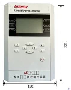
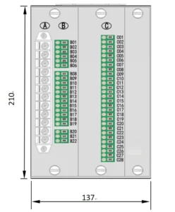
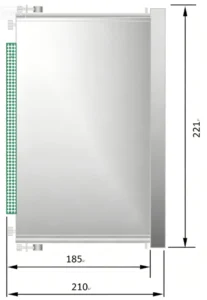
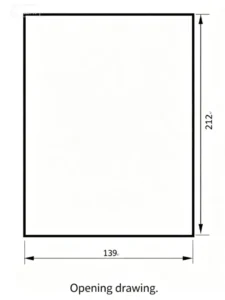
Outline and Installation Dimensions
FAQ
1. What is an ANSI 87L protection relay?
ANSI 87L is the designation for line current differential protection. Its core principle is to compare currents at both ends (or multiple ends) of a line, detect internal faults, and trip instantaneously. It typically serves as the primary protection for transmission lines.
2. How does the ASL-441XLH line differential protection work?
As an 87L relay, it exchanges real-time current data with the remote terminal(s) via communication channels and calculates the differential current. When the differential current exceeds the threshold defined by the restraint characteristic, it is identified as an internal fault and the relay initiates a trip.
3. What protection functions are integrated into the ASL-441XLH?
In addition to the 87L main protection, such devices typically integrate backup functions such as overcurrent, earth fault protection, as well as auxiliary functions like circuit breaker failure and auto-reclosing. For specific functions, please refer to the official technical manual or function list of this model.
4. What communication interfaces are available for the ASL-441XLH?
It is typically equipped with fiber-optic interfaces for 87L differential communication, as well as Ethernet, RS-485, etc., for substation-level communication, supporting standard protocols such as IEC 61850. For the exact interface types and quantities, please consult the product specification sheet.
5. What happens if the 87L communication channel fails?
When communication is lost, the 87L differential protection is usually blocked and disabled, with an alarm signal issued. Backup protections (e.g., distance, overcurrent) must then clear any faults. If “permissive” or “direct transfer trip” logic is used, channel failure may also affect coordination functions.
6. Why are CT ratio and polarity important for 87L protection?
Inconsistent CT ratios will result in incorrect differential current calculations, while reversed polarity will misalign the current vector directions at both ends, potentially causing relay maloperation or failure to trip. Therefore, CT parameters must be matched and polarity must be correctly verified during configuration.
7. What are the main 87L protection settings?
Key settings include: differential pickup, slope coefficients (K1, K2), breakpoint current, as well as CT ratio and channel delay compensation. These settings must be calculated based on line parameters and system impedances. Final settings must be based on the approved project setting calculation report.
8. How is the ASL-441XLH commissioned?
Typical steps include: ① CT polarity and secondary circuit inspection; ② communication channel test and delay measurement; ③ relay single-device testing; ④ load test (checking differential current). For detailed commissioning procedures and acceptance criteria, strictly follow the device’s commissioning guide.
9. Can the ASL-441XLH provide backup protection?
Yes. It typically integrates backup elements such as phase overcurrent and earth overcurrent, which can operate with a time delay for faults on the protected line or adjacent equipment. For specific backup protection functions, refer to the protection function configuration table of this model.
10. What information is required to configure an ASL-441XLH relay?
Typically: ① Primary system parameters (line impedance, CT ratio/polarity); ② Protection settings (differential pickup, slope coefficients, etc.); ③ Communication parameters (channel type, address, delay). For a detailed configuration checklist and software operation guide, always refer to the device’s user manual.
2 reviews for ASL-441XLH 87L Protection Relay
Related products
High Quality
Stable performance, reliable design, ensuring safe operation for power system protection and grid stability.
Fast Delivery
Timely delivery to support your urgent orders and project schedules efficiently and professionally at any time.
Best Warranty
Professional Warranty: Reliable after-sales support for stable relay protection and long-term customer satisfaction.
xiao zhang –
Line differential protection relay (ANSI 87L) features outstanding anti-CT-saturation performance and high sensitivity for internal short-circuit faults. Real-time bidirectional current data exchange ensures reliable discrimination between in-zone and out-of-zone faults; multiple communication interfaces available for global transmission line projects.
Jack –
Accurate protection settings, clean trip operation — no misoperation or failure to operate.