
-
Leon Zhang sales consultant
-
Email: zxl635973785@gmail.com
-
Phone/WhatsApp: +86 13655813266
PLC Programming: A Practical Guide
PLC programming produces a cyclic task: copy inputs, run the program, write outputs, repeat. Five IEC 61131-3 languages exist, and two of them carry most plants. This guide covers language choice, symbolic addressing, timers, testing and where a controller should step aside for a safety device.
PLC programming writes the logic that an industrial controller executes on every scan, and most controllers finish that scan in 5 to 20 ms. The work follows IEC 61131-3:2013, which defines five languages. Most plants need only two of them. What follows covers language choice, addressing, timers, testing and commissioning.
At a glance
- PLC programming produces a cyclic task, not an application: the controller re-runs the whole program from the top every scan.
- IEC 61131-3:2013 defines the five languages. IEC 61131-1:2003 fixes the terms, and IEC 61131-2:2017 covers the hardware tests.
- Ladder logic wins discrete control because an electrician can read it, and it maps onto relay schematics one rung at a time.
- Structured text carries arithmetic, strings and arrays, and it is the comfortable option for PID maths and recipes.
- Address every point symbolically. A tag such as Pump1_Run beats %I0.3 once the panel gains a second pump.
- Every timer needs a reset path, otherwise a warm restart leaves it part elapsed and the sequence hangs.
- Simulate before steel is live. A decent simulator catches most logic faults long before commissioning week.
- A forced output left on across a shift handover has hurt people. Log every force and clear it the same day.
What PLC Programming Actually Produces
The output of this work is not a file sitting in a folder. It is compiled machine code plus a variable table, downloaded into the controller and executed whenever the scan reaches the task that owns it. Cut power for a year, restore it, and the controller starts the same task again without a single typed command.
That difference shapes everything downstream.
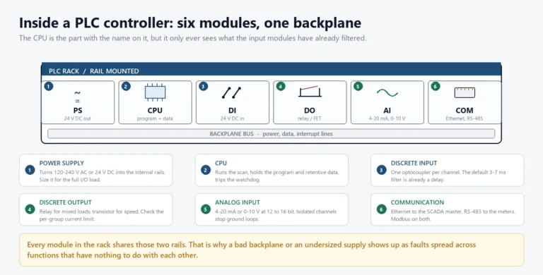
Three kinds of memory hold the work. Volatile RAM keeps the running image and the live process state, retentive memory survives a power cut with timers and latches intact, and non-volatile storage keeps the download ready for the next cold start. Downloads and edits differ too. A full download replaces everything and stops the controller for a few seconds, while an online edit swaps one block while the machine keeps running.
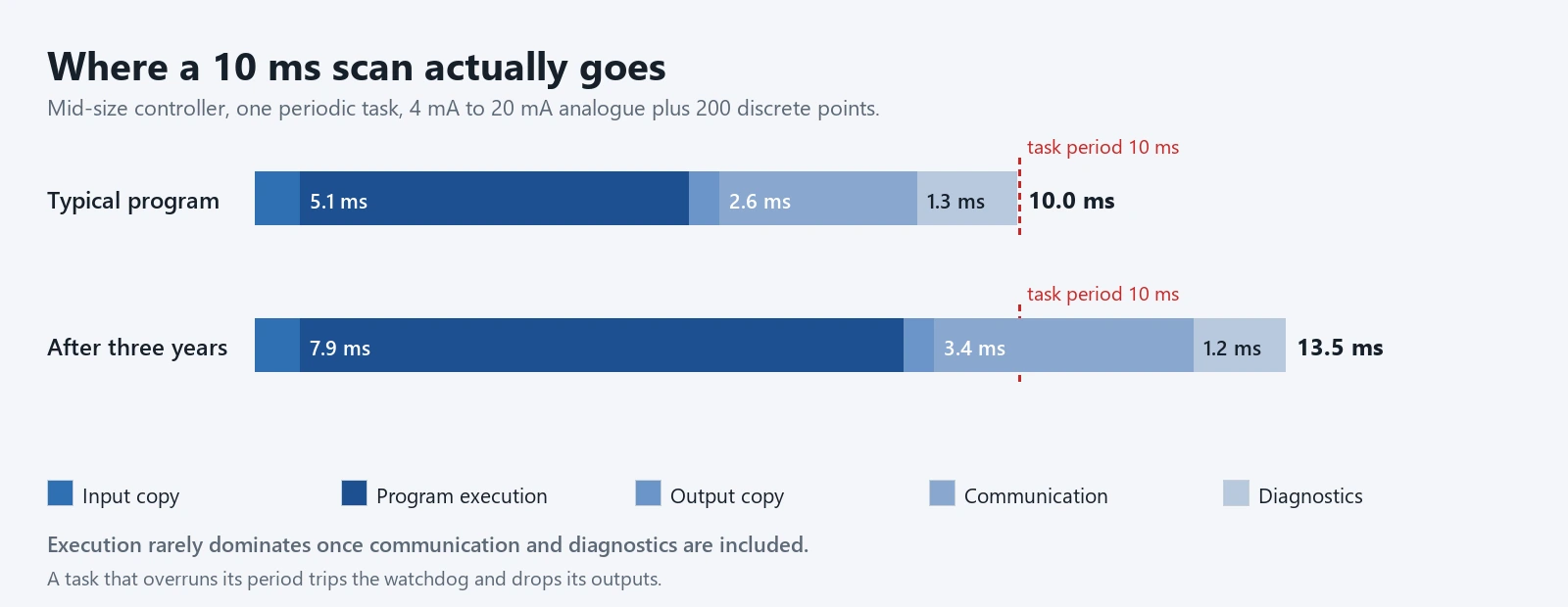
A desktop application reacts to events. A controller program runs on a fixed cycle: copy inputs, execute every reachable network, write outputs, then handle diagnostics and communication. Each pass through that cycle is one scan. Scans land between 5 and 20 ms on a mid-size controller. A large program on an old CPU can reach 80 ms, and that number changes what the machine can do.
Execution is deterministic, so time becomes a design input rather than a symptom. A proximity sensor pulsing for 4 ms will slip straight past a 20 ms scan. Nobody fixes that by writing tighter code. The fix is a faster task, a hardware interrupt, or an input card that latches the pulse until the program asks for it.
One consequence follows. Clever code loses to code that a maintenance electrician can read at 2 a.m. by torchlight, holding a printed rung sheet. When those two goals clash, read the second one again.
Common PLC Uses Across a Plant
Four jobs show up in almost every program, whatever the industry.
- Starting and stopping sequences for motors, with interlocks that keep two contactors from pulling in together.
- Permissive chains, where a pump only runs when suction pressure, valve position and a seal-water signal all agree.
- Batching and dosing, where quantities repeat by recipe and change with the product.
- Monitoring and alarming, where the program watches analogue values and raises an alarm before the process drifts out of range.
A fifth job appears in power plants. Protection itself stays in the relays, while the controller handles the sequence: start permissives, valve movement and the reports operators read. That split, protection to relays and sequence to the controller, holds in a water plant and in a hydropower station alike.
The Five Languages Inside IEC 61131-3
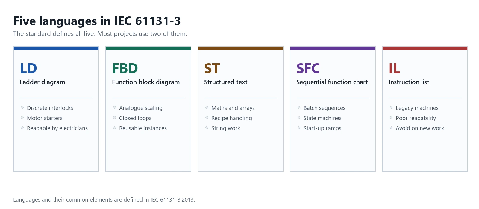
IEC 61131-3:2013 defines five languages, and a controller rarely needs more than two. Picking the pair early saves a rewrite later, because mixing all five in one project is how programs become unmaintainable.
| Language | Looks like | Reach for it when | Where it hurts |
|---|---|---|---|
| LD, ladder diagram | Relay rungs with contacts and coils | Discrete interlocks, motor starters, permissive chains | Arithmetic and string work get unreadable fast |
| FBD, function block diagram | Blocks wired together with signal lines | Analog scaling, closed loops, reusable function blocks | Large sheets sprawl past one printed page |
| ST, structured text | Pascal-like statements | Maths, arrays, recipes, string handling | A technician reading it needs training first |
| SFC, sequential function chart | Steps, transitions and branches | Batch sequences, state machines, start-up ramps | Simple on and off logic gains ceremony |
| IL, instruction list | Assembly-style opcodes | Legacy programs nobody wants to rewrite | Deprecated in practice; poor readability |
The table hides one practical rule. Discrete work with more than twenty devices belongs in ladder. Anything with a floating-point number in it belongs in structured text. A plant that follows that split rarely argues about style.
Ladder Logic, Still the Default for Discrete Control
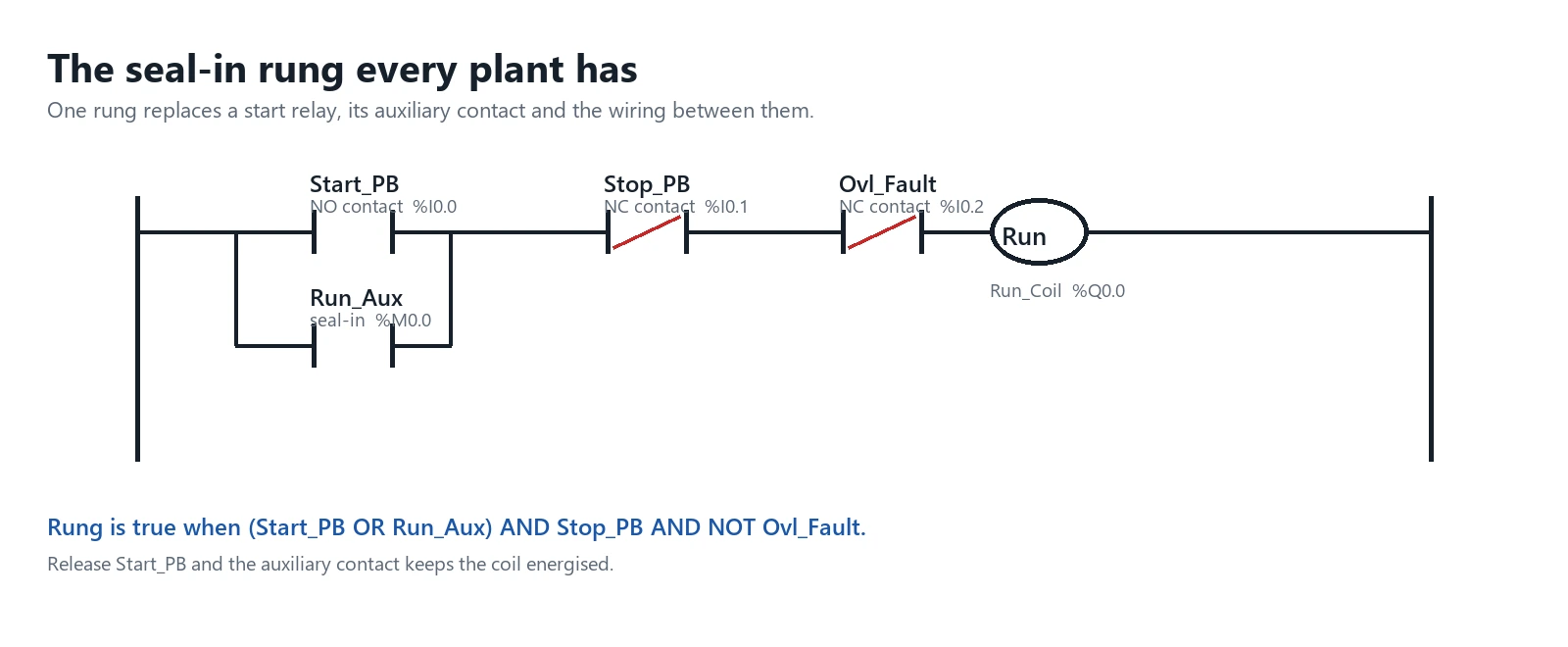
Ladder survived because it copies the relay diagrams that came before it. A normally open contact is drawn as two parallel bars, a normally closed one has a diagonal slash, and a coil is a circle. The program reads left to right, top to bottom, exactly as current would flow through a hardwired panel.
Figure 2 shows the rung every plant has. Start_PB and a seal-in contact from the motor contactor sit in parallel, Stop_PB sits in series, and Run_Coil drives the output. Release Start_PB and the auxiliary contact keeps the coil energised until Stop_PB opens or the overload drops out.
Three habits keep ladder readable. Name every contact after the device, not the address. Keep one physical output per rung. Never let a coil appear twice in the same program, because the last rung evaluated wins and the fault takes days to find.
Output hardware decides what the coil can actually switch. A relay output passes 230 V AC at a few amps and ignores polarity, while a transistor output switches 24 V DC in under 1 ms and dislikes an inductive load without a suppressor. Solid-state relays sit between the two. Match the output to the device and read the nameplate full load current on the contactor before committing, because motor inrush on a direct start can run six times the steady figure.
Welded contacts defeat every one of them.
A contactor that has interrupted a stalled motor often fuses its contacts shut, so the auxiliary feedback keeps reporting stopped while the machine runs. Simulators never show that fault, which is why proving out every feedback contact against the field device matters more than proving the logic.
Structured Text Carries the Arithmetic
Scaling a 4 mA to 20 mA level transmitter into a usable number takes one line in structured text and four blocks in ladder. The same applies to a rolling average, a pump duty swap, or a recipe table with sixteen ingredients.
Six lines replace a dozen rungs. The trade-off sits with the maintenance team, who have to read it. Keep structured text in small, clearly named function blocks and expose the result to the ladder logic as a single contact or value.
Function Blocks and Steps: FBD and SFC
Function block diagram suits analogue control. A PID block, a scaling block and a limit block wire together on one sheet, and the signal names tell the story. Every block has an instance, so the same PID logic runs on four valves without copying code.
Sequential function chart suits anything with steps. A clean water start-up has fill, mix, heat, hold and discharge, with a transition guarding each move. Drawing those five steps once beats writing the same latch and reset pattern in ladder twenty times.
Plants that skip both tend to rebuild them badly inside ladder, with a step integer and a dozen comparison contacts. That works. Then someone edits it in year three, and it stops working.
PLC Manufacturing Environments: What Carries Over
Programs written for one industry rarely transfer as files, but the habits transfer completely.
A car body line and a pump station both care about cycle time, both hide faults behind a sealed panel, and both punish an undocumented force. Food plants add washdown constraints and a clean-in-place sequence. Water plants add long cable runs and a SCADA master that must keep seeing a heartbeat. Power stations add switching interlocks and a change process that treats a program edit the way operations treats a switching order.
Reading programs from a different industry on purpose is the fastest way to pick those habits up.
Choosing PLC Programming Software Without Buying a Cage
PLC programming software is the one part of the system the plant cannot shop around for. Each vendor compiles to its own runtime, so the licence decision outlives the hardware decision by a decade.
Five questions settle it. Does the package simulate without hardware. Can two engineers compare two versions of the same block. Does it check the program against the installed module list before download. How are seat licences renewed. And what does the offline emulator cost in year five.
Ask about export too. A tool that writes out the source as plain text lets the plant archive it, diff it, and hand it to a contractor later. A tool that only knows its own project file holds the plant’s logic hostage.
Licence models age badly. A perpetual seat tied to a hardware dongle locks the program to one laptop that nobody wants to keep, while a subscription quietly stops authorising on a site with no internet access. Each model suits a different buyer. A plant that edits twice a year wants the cheapest perpetual licence it can find, and a builder shipping ten panels a month wants a subscription that covers every firmware revision. Ask the vendor what happens to the licence when one machine is retired and its program is loaded into the replacement panel, because that is the day the real cost arrives.
Nobody budgets for it, and everybody meets it.
Addressing: Symbolic Tags Beat Raw I/O Points
Raw addresses were fine when a program had forty points. A water plant with 800 tags and three programmers does not survive them, because %I0.3 means nothing to anyone reading the rung sheet six months later.
| Symbolic tag | Direct address | What it means | Cost of getting it wrong |
|---|---|---|---|
| Pump1_Run_FB | %I0.3 | Auxiliary contact on starter 1 | A wrong feedback keeps a standby pump waiting |
| Level_Raw | %IW64 | Unscaled 4 mA to 20 mA input | Two engineers scale it differently |
| Valve3_Open_Cmd | %Q1.7 | Solenoid drive for valve 3 | A forced bit opens a valve nobody expects |
| Trip_Latch | %M12.4 | Retentive trip memory | Clearing it on power up hides the cause |
| Comm_Timeout | %M40.0 | SCADA heartbeat lost | Plant keeps running with no supervision |
Pick a naming convention on day one and write it down. Device, function and signal type in that order covers most cases. Treat retentive memory as a scarce resource: every bit that survives a power cycle needs a documented reset path, or the plant will chase a trip that happened in 2024.
Analogue points need separate attention. A 4 mA to 20 mA level input arrives as a raw integer, usually 12 bit or 16 bit, and every scaling block in the program has to use the same range. Zero drift arrives slowly: a transmitter sitting at 3.8 mA on an empty tank eventually crosses the low alarm at rest, and the team reads it as a nuisance trip and silences the alarm instead of recalibrating. A differential pressure transmitter across a strainer has the same problem in miniature, because the useful signal often lives inside the first 10 % of span.
Timers, Counters and Three Scan-Time Traps
A timer in a controller has no clock of its own. It accumulates elapsed time by looking at the system clock once per scan, so a 100 ms preset on a jittery task can fire anywhere between 100 ms and 100 ms plus one scan.
| Instruction | Typical preset | Usual job | Common trap |
|---|---|---|---|
| TON, on-delay | 0.5 s to 60 s | Debounce, start delays | Reset never reaches it after a fault |
| TOF, off-delay | 1 s to 30 s | Run-on fans, seal decay | Output stays live after an emergency stop |
| TP, pulse | 200 ms to 2 s | Horn bursts, lamp tests | Retriggering extends the pulse unexpectedly |
| CTU, count up | 10 to 10000 events | Starts per hour, batch counts | Counter overflows into a false zero |
Three traps account for most timer faults seen on site. A timer in a slow task drifts. A reset rung placed below the timer only clears it on the next scan. And a retentive timer survives a restart with its accumulator intact, so the machine resumes mid-sequence.
Debounce belongs in hardware where you can get it.
A float switch bouncing for 20 ms on a slow-filling tank produces hundreds of transitions an hour, and every one lands in a counter someone resets by hand. Input cards that offer a configurable digital filter remove the problem before it reaches the program. Where no filter exists, a short software time-delay works, costs scan time, and needs its own comment so the next programmer knows why the value looks wrong.
Program Structure: Tasks, POUs and the Cycle Budget
A controller runs tasks, and each task holds programs. A program holds program organisation units, and a POU holds the networks, functions and blocks. Splitting work that way lets a 10 ms task carry interlocks while a 250 ms task carries analogue loops and reporting.
Fast task, slower task, then everything else. Three tiers cover nearly every machine. Reserve the fast tier for outputs that must react inside 10 ms, because every network dropped into it costs scan time the rest of the program needs.
Watch the watchdog. A task that overruns its period gets killed, outputs fall to their configured state, and the plant sees a stop with no obvious cause. Programmers who leave 40 % headroom on the cycle budget rarely meet that fault.
Testing Before Steel Is Live
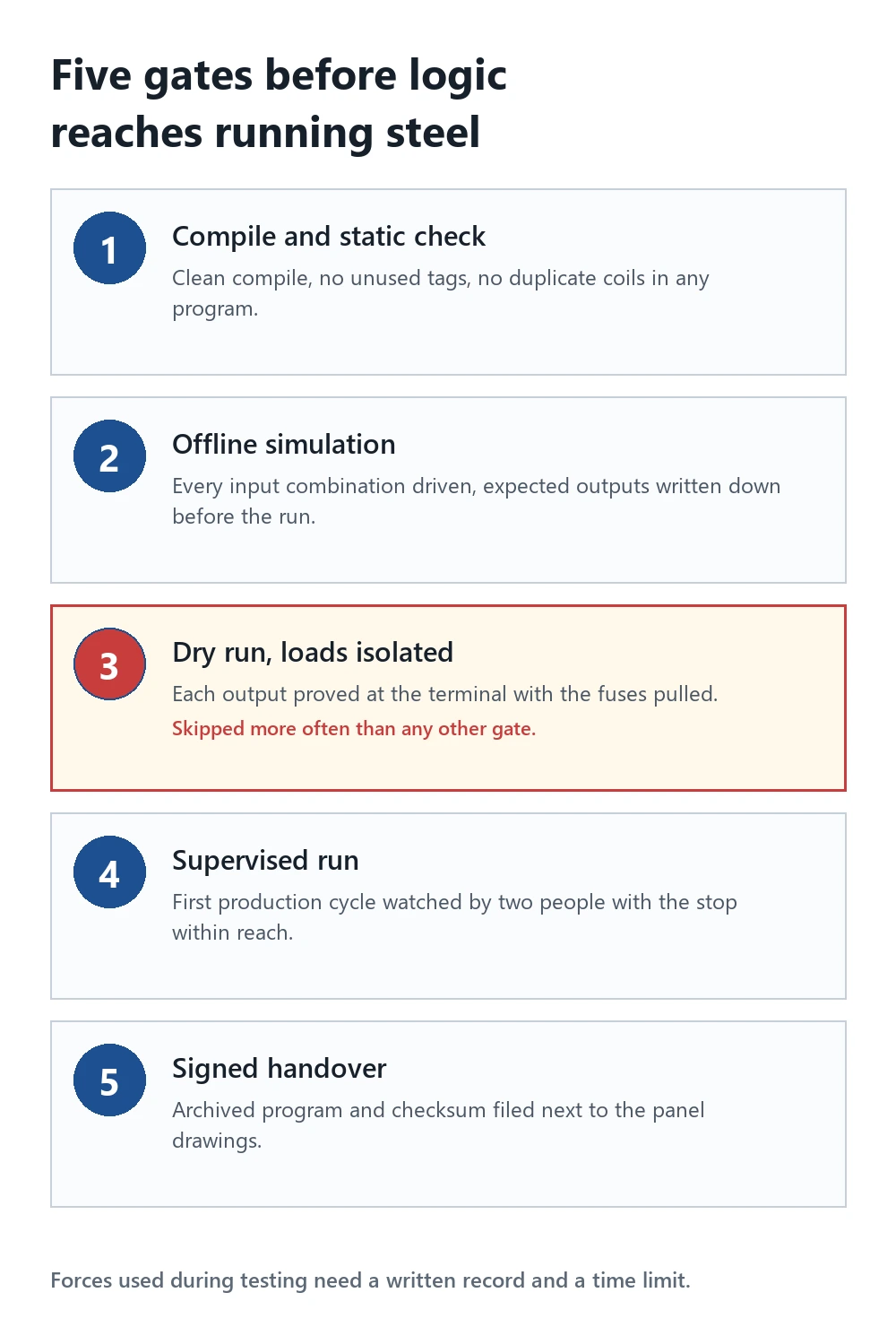
A simulator runs the controller logic on a laptop with no cabinet attached. It finds reversed contacts, missing resets and dead-end rungs. It does not find a sensor wired to the wrong terminal, a contactor whose coil needs 230 V AC while the card gives 24 V DC, or a limit switch mounted upside down.
So the test plan has two halves. Prove the logic offline with a table of input combinations and expected outputs. Then prove the wiring with the cabinet open, one device at a time, with the output fuses pulled where the motion can hurt someone.
Forcing is the sharpest tool in that second half and the one most often misused. A forced input hides the real device. A forced output moves the machine. Both need a written record, a time limit, and a second person who knows they are in force.
Two field faults deserve their own lines.
A feedback point stuck on usually means wiring, not mechanics, and most often a short-circuit to a live terminal at a crowded gland plate. Then there is the pump that runs for 200 ms and stops, which points at the program long before it points at the machine.
Where PLC Programming Meets Functional Safety
Safety functions do not live in the general-purpose CPU unless that CPU is safety rated. ISO 13849-1:2023 sets performance levels for safety-related control parts, while IEC 62061:2021 and IEC 61508-1:2010 set the SIL route. A standard controller doing a safety stop is the wrong answer at any of those levels.
The usual arrangement splits the work. The standard controller runs the process. A safety PLC or a hardwired trip chain handles the stop, using redundant inputs and monitored outputs, and it reports status over to the standard program. Emergency stop chains stay hardwired through the contactor coil where the standard allows it.
Write the boundary down. Which outputs are safety related, which are not, and what happens to each on a stop. ANSI device numbers help here, and ANSI/IEEE C37.2-2022 gives the numbers most drawings already use for the 86 lockout and 94 trip functions.
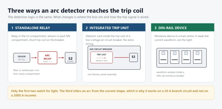
The mechanical side still does the stopping. A safety relay interrupts the contactor coil and, on larger machines, drives a shunt trip on the breaker rather than tripping through firmware alone. Latching matters when the stop clears: once a stop is latched, restarting takes a deliberate reset at the machine instead of the casual return of one permissive contact.
When PLC Programming Is the Wrong Answer
A controller is not the answer to every control problem. Five boundaries come up repeatedly, and each one has a cheaper or a safer alternative.
- The function needs SIL 2 or higher. Put it on a safety-rated controller or a hardwired trip chain, not on the general CPU.
- The response must land inside 1 ms. Hardwire it, or use an input card with its own interrupt and latch.
- Nobody at the site can read the program. Relay logic or a fixed-function relay costs less than a controller nobody maintains.
- The job is logging and reporting at one-second resolution. That belongs in the SCADA or historian layer, not in the scan.
- The process is a single motor with two pushbuttons. A contactor and an overload relay do the job for a fraction of the price.
Each of those boundaries says the same thing. Controllers earn their place where logic changes, where many devices interact, or where supervision matters. Once a machine stops having those three properties, the relay panel wins on cost and on clarity.
Commissioning: Six Checks With the Cabinet Open
Commissioning is where a program meets the plant it was written for. Six checks catch the faults that simulation cannot see, and they take under an hour on a small panel.
- Confirm every input changes state at the controller when the device moves, using the live watch table and not the LED.
- Drive each output once from the program with the load disconnected, then reconnect and repeat.
- Trip the emergency stop with the machine at speed and measure the stopping time against the risk assessment.
- Pull the communications cable and confirm the plant goes to its defined state rather than holding the last command.
- Cycle power twice and check that retentive data, timers and latched trips all behave as documented.
- Archive the downloaded program with its checksum, and store it with the panel drawings.
Six checks, one hour, and the most common commissioning faults never reach a production shift. Skipping the last one is how a panel ends up running software nobody has a copy of.
Conclusion
PLC programming is a trade skill before it is a software skill. The code has to survive shift changes, a substituted contactor, and a panel built fifteen years later by someone who never met the author. Two languages cover most plants: ladder for discrete logic, structured text for anything with a decimal point. Symbolic tags, a documented reset path for every timer, and a simulation run before energising do more for uptime than any clever algorithm.
Where the work touches a safety function, the controller steps aside for a safety-rated device. Pump station control panels built around this split ship with the two layers drawn separately, and the pump station automation guide shows how the program meets the field devices. For the supervisory layer, see the SCADA guide and the note on Modbus and IEC 61850 protocols.
Frequently asked questions
What is PLC programming?
PLC programming creates the instructions a programmable controller executes on every scan, using one or more of the five languages defined in IEC 61131-3:2013.
Which language should a beginner learn first?
Begin with ladder logic, because it maps onto relay schematics and covers most discrete work, then add structured text for arithmetic and string handling.
How long does it take to learn?
An electrician usually writes useful rungs after two weeks of guided practice, while reading a program with several thousand networks comfortably takes about a year of plant work.
Can a controller run Python or C?
The real-time task accepts the IEC 61131-3 languages, so Python or C stay on the engineering station or a supervisory computer rather than inside the scan.
Must the software come from the controller vendor?
In practice yes, because each vendor compiles to its own runtime, while IEC 61131-3 makes the logic portable between platforms but not the project file.
Why does a program pass simulation and still fail on site?
Field faults usually come from wiring polarity, contact bounce, or a scan longer than the pulse the sensor produces, and none of those appear in a simulation.
What does the software cost?
Entry-level packages are free or nearly so, while a full engineering suite with simulation and safety support can cost several thousand dollars per seat and renews annually.
Can the program be edited while it runs?
Most controllers accept online edits, though a download on a running machine can drop outputs for one scan, so plants restrict online changes to a permitted window.
Related reading
- Pump station automation and SCADA control
- PLC control panel for hydropower and pumping stations
- SCADA systems, a practical guide
- Modbus and IEC 61850 communication protocols
- PLCopen, the IEC 61131-3 user organisation
Sources and standards
| Source | Standard | Edition | What it covers |
|---|---|---|---|
| IEC | IEC 61131-3 | 2013 | The five programming languages and their common elements |
| IEC | IEC 61131-1 | 2003 | General information and definitions |
| IEC | IEC 61131-2 | 2017 | Equipment requirements and tests |
| IEC | IEC 61508-1 | 2010 | Functional safety of electrical and programmable systems |
| IEC | IEC 62061 | 2021 | Safety-related control systems for machinery |
| ISO | ISO 13849-1 | 2023 | Design of safety-related parts of control systems |
| IEEE | ANSI/IEEE C37.2 | 2022 | Device function numbers used on drawings |
About Author

Hello, I'm Leno Zhang. I have 15 years of experience in the power relay protection industry with extensive pre-sales and after-sales project experience. Our company specializes in various complete sets of relay protection and automation equipment. I can assist customers in solving all practical on-site project challenges and provide optimal integrated solutions.
Tell Us Your Requirement
High Quality
Stable performance, reliable design, ensuring safe operation for power system protection and grid stability.
Fast Delivery
Timely delivery to support your urgent orders and project schedules efficiently and professionally at any time.
Best Warranty
Professional Warranty: Reliable after-sales support for stable relay protection and long-term customer satisfaction.