

-
Leon Zhang sales consultant
-
Email: zxl635973785@gmail.com
-
Phone/WhatsApp: +86 13655813266
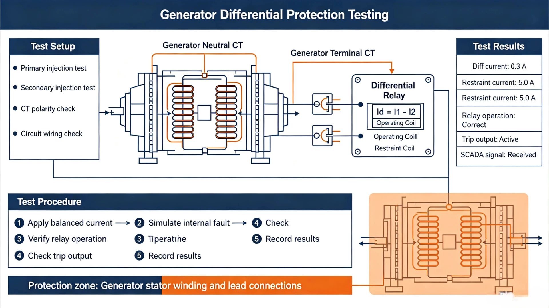
Generator Differential Protection Testing: Methods, Procedures and Test Cases
What Is Generator Differential Protection Testing?
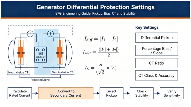
Generator differential protection testing is the core commissioning and maintenance procedure to verify the full functionality of the 87G generator differential protection system. It validates that the differential relay, CT secondary circuits, protection logic, alarm modules, and generator breaker trip chain operate reliably for internal faults and remain stable during external system disturbances.
Unlike simple relay parameter checking, systematic 87G testing covers hardware circuit verification, algorithm characteristic calibration, fault simulation, and end-to-end trip validation. It eliminates commissioning defects, CT mismatches, and configuration errors that cause relay mal-operation or refusal-to-trip during generator operation.
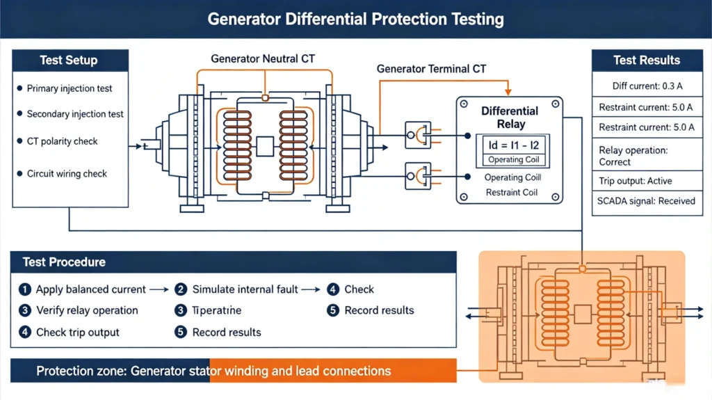
Key Takeaways
- Field generator differential protection testing mainly adopts secondary injection testing, with primary end-to-end testing applied for critical large-capacity generator units.
- Qualified testing must verify two core performances: sensitivity to internal short-circuit faults and stability against external through faults.
- CT ratio, polarity, phase sequence, wiring integrity, and relay preset settings are mandatory preconditions for valid functional testing.
- Differential and restraint characteristic tests require multi-point calibration, rather than single pickup value verification, to match actual operating conditions.
- Final commissioning confirmation must cover the full protection chain from CT signal acquisition to generator breaker tripping.
Test Items for Generator Differential Protection
All test items are standardized per IEC and IEEE generator protection specifications, covering circuit, relay logic, fault response, and trip execution. The full test scope ensures no missing links in on-site commissioning and routine maintenance.
| Test Item | Core Testing Purpose |
|---|---|
| Relay Settings Verification | Confirm consistency between on-site relay parameters and approved protection setting sheets |
| CT Ratio Verification | Verify current transformation accuracy to avoid differential current deviation |
| CT Polarity Test | Ensure correct current direction to prevent false differential current generation |
| CT Wiring & Phase Check | Eliminate phase dislocation and terminal connection errors in primary/secondary circuits |
| Differential Pickup Test | Calibrate the minimum operating current of 87G differential protection |
| Bias/Slope Characteristic Test | Verify protection threshold changes under different restraint current levels |
| Internal Fault Simulation | Confirm reliable tripping response of protection against generator zone faults |
| External Fault Stability Test | Verify no mal-operation during external through faults and large current impact |
| CT Saturation Stability Test | Check protection anti-interference capability under CT transient saturation conditions |
| Trip Output Circuit Test | Validate the integrity of relay trip signal to generator breaker execution path |
| Alarm & Communication Test | Confirm correct SCADA signal upload and local alarm indication |
| End-to-End Test | Full-link verification of CT, relay, communication and trip system |
Complete Generator Differential Protection Testing Procedure
The on-site testing process follows a strict Pre-Test Preparation → Static Circuit Test → Relay Characteristic Test → Fault Simulation → Trip Verification → Final Confirmation sequence, which is the standard commissioning workflow for EPC projects and power plant O&M.
Pre-Test Data Review & Preparation
All formal testing must be based on official design documents and setting sheets, not blind relay injection tests. Prepare and verify the following data before testing:
- Generator rated parameters: power capacity, rated voltage, rated primary current
- CT parameters: ratio, accuracy class, secondary rated current, connection mode
- Relay information: model, firmware version, factory default logic
- Approved protection settings: differential pickup value, bias slope coefficient, high-set differential threshold, operating time limit
- Project drawings: generator protection schematic, CT secondary wiring diagram, trip circuit diagram
- Field equipment status: generator breaker, auxiliary relay, trip coil operating condition
Core Engineering Principle: Testing should begin with the approved protection setting sheet and protection schematic, not with relay injection alone.
Relay Settings Verification
Compare on-site relay configured parameters with official setting values one by one to eliminate configuration errors. This step is linked to the previous technical article Generator Differential Protection Settings, ensuring consistent setting logic and on-site execution.
Key verification parameters:
- CT ratio and secondary current calibration
- Differential pickup current and high-set differential current
- Percentage bias slope and restraint current threshold
- Protection operating time and delay logic
- Fault blocking, alarm triggering and trip outlet logic
- Binary I/O port assignment and SCADA signal mapping
CT Circuit Static Testing
CT circuit abnormality is the most common cause of 87G protection mal-operation. All CT tests comply with IEC 61869-2 and IEEE C57.13 standards, covering ratio, polarity, wiring and insulation performance.
CT Ratio Test
Verify the actual transformation ratio matches the design value to avoid persistent deviation of differential current. The ratio calculation formula is as follows:
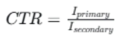
Taking a common 50MW generator as an example: the configured 3000/5 A CT has a standard ratio of 600. The test allows a tolerance within ±1%, beyond which CT replacement or parameter recalibration is required.
CT Polarity Test
Correct CT polarity ensures that the current vectors of the generator stator terminal side and neutral side are consistent under normal load and external fault conditions. Reverse polarity will directly cause:
- Abnormal residual differential current under normal generator operation
- Loss of stability during external through faults, triggering false tripping
- Distorted relay differential-restraint characteristic judgment
On-site testing adopts the pulse polarity method to confirm P1/P2 primary terminals and S1/S2 secondary terminals correspond correctly for all three phases and neutral-side CTs.
CT Wiring & Phase Identification
Check one by one the consistency of phase A/B/C wiring for terminal-side and neutral-side CTs, confirm no phase crossing or wrong connection of secondary loops, and verify reliable grounding of CT secondary terminals. This step eliminates wiring defects in construction handover.
CT Secondary Circuit Insulation & Performance Test
The CT secondary loop’s insulation, continuity and burden directly determine the signal acquisition accuracy of differential protection. Mandatory test items include:
- Insulation Resistance Test: Use a 1000V insulation tester to detect secondary loop insulation to ground, with qualified value ≥1MΩ.
- Loop Continuity Test: Confirm no open circuit or virtual connection in the secondary wiring loop.
- Secondary Resistance & Burden Test: Verify actual CT burden is lower than the rated burden to avoid measurement distortion.
- Grounding Verification: Confirm single-point grounding of CT secondary loops to prevent circulating current interference.
Safety Reminder: CT secondary circuits must not be opened when the primary side is energized, to prevent high-voltage breakdown of secondary equipment and personal injury accidents. All tests comply with field safety procedures and manufacturer specifications.
Secondary Injection Testing (Core Functional Test)
Secondary injection testing is the mainstream and most reliable 87G protection commissioning method. It injects precise current and phase angle signals directly into the relay input terminals, simulating generator operating and fault conditions without energizing primary equipment, and fully verifying relay algorithm characteristics.
Required Test Equipment
- Three-phase universal protection relay test set
- Digital multimeter and 1000V insulation tester
- CT parameter analyzer
- Industrial laptop (relay configuration and data recording)
- Insulated test cables and standard test terminal blocks
Differential Pickup Test
Test the minimum differential current that triggers 87G protection operation, verifying the basic sensitivity of the protection. The operating logic follows:
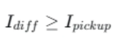
Test steps: Inject balanced three-phase restraint current, slowly increase the differential current, record the actual pickup value of each phase, and compare with the setting value (allowable tolerance ±3%).
| Test Phase | Expected Pickup Current | Measured Value | Test Result |
|---|---|---|---|
| Phase A | Approved setting value | Field measured data | Pass/Fail |
| Phase B | Approved setting value | Field measured data | Pass/Fail |
| Phase C | Approved setting value | Field measured data | Pass/Fail |
Bias/Slope Characteristic Test
Single pickup test cannot verify the full operating characteristic of differential protection. The percentage bias slope determines the protection’s anti-interference ability under high through-current conditions. The standard relay operating criterion is:

Where: Idiff = differential current, Irest = restraint current, S = bias slope coefficient. The specific algorithm varies slightly by relay manufacturer, but the test logic is unified.
Multi-point calibration is required to cover low, medium and high restraint current working conditions, matching actual grid fault scenarios:
| Test Point | Restraint Current Level | Differential Current Setting | Expected Relay Response |
|---|---|---|---|
| 1 | Low | Below characteristic threshold | No Trip |
| 2 | Low | Above characteristic threshold | Trip |
| 3 | Medium | Below characteristic threshold | No Trip |
| 4 | Medium | Above characteristic threshold | Trip |
| 5 | High | Above characteristic threshold | Trip |
Internal Fault Simulation Test
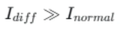
Simulate typical internal faults in the generator protection zone (phase-to-phase, phase-to-ground, three-phase short circuit) to verify protection sensitivity. Under internal fault conditions, the current vectors of terminal-side and neutral-side CTs are unbalanced, producing a large differential current:
Qualified performance: The relay quickly identifies the fault, activates the trip logic, outputs fault alarms, and records complete fault wave and event logs, consistent with design protection characteristics.
External Fault Stability & CT Saturation Test
External faults occur outside the generator protection zone. Large through-current may cause transient saturation of CTs, resulting in inconsistent current transformation on both sides and false differential current. This test verifies the core stability of 87G protection.
Test content: Simulate high-magnitude external through-current, CT ratio mismatch and transient saturation scenarios. Qualified standard: The protection relies on bias slope restraint logic to avoid mal-operation, ensuring stable operation during external grid faults.
The bias slope design of high-quality generator differential relays can effectively suppress false differential current generated by CT saturation, which is the key to preventing false tripping of generator main protection.
Full Trip Circuit Verification
Relay pickup alone cannot prove the complete protection system is effective. Field testing must verify the full trip chain:
Relay trip output → Lockout relay → Trip coil → Generator breaker mechanical tripping → SCADA signal upload
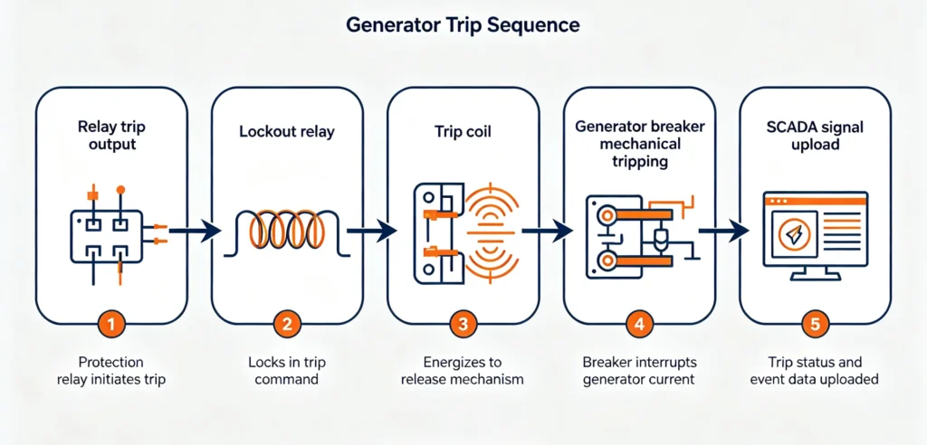
Key verification points: Trip contact integrity, trip circuit supervision function, lockout relay reset logic, breaker auxiliary contact state change, and remote alarm indication. Eliminate hidden dangers such as poor contact of intermediate relays and stuck breaker mechanisms.
Core Engineering Conclusion: A successful relay pickup test does not prove that the complete generator protection trip chain is functional.
End-to-End Testing
For large-capacity generators and complex differential protection schemes, end-to-end testing is mandatory. It penetrates the entire protection link including on-site CTs, signal cables, protection relays, time synchronization systems and trip execution devices, verifying the overall coordination performance of the system under real operating conditions.
Field Test Case (50MW Generator Unit)
The following is a standardized test case for a commercial 50MW generator unit, covering all core test items, with reference value for EPC project commissioning and daily O&M testing.
| Generator & Protection Parameter | Field Actual Configuration |
|---|---|
| Rated Capacity | 50 MVA |
| Rated Voltage | 11 kV |
| Rated Primary Current | 2624 A |
| CT Ratio | 3000/5 A |
| Protection Function | 87G Generator Differential Protection |
Test results summary (all items meet standard tolerance requirements):
| Test Item | Expected Standard | Test Result |
|---|---|---|
| CT Ratio & Polarity | No deviation, correct phase | Pass |
| Differential Pickup Value | Within ±3% setting tolerance | Pass |
| Bias Slope Characteristic | Multi-point calibration compliant | Pass |
| Internal Fault Response | Reliable tripping | Pass |
| External Fault Stability | No mal-operation | Pass |
| Full Trip Circuit | Breaker trips normally, signal normal | Pass |
Common Field Testing Problems & Troubleshooting
Relay Mal-Trip During External Fault Simulation
Main causes: Reverse CT polarity, phase sequence dislocation, excessive CT saturation, unreasonable bias slope setting, inconsistent CT transformation accuracy on both sides. Solution: Recheck CT wiring calibration, adjust slope parameters, and replace unqualified CTs.
No Trip During Internal Fault Simulation
Main causes: Excessively high differential pickup setting, wrong CT ratio configuration, blocked protection logic, incorrect test current output, phase mapping errors. Solution: Recheck relay setting sheets and wiring diagrams, clear fault blocking signals, and recalibrate test equipment.
Abnormal Differential Current Under Normal Load
Main causes: CT polarity errors, secondary loop virtual connection, inconsistent CT aging degree, residual magnetism of CT core, relay parameter mismatch. Solution: Perform secondary loop full inspection and CT degaussing treatment.
Data Deviation Between Test Set and Relay Software
Deviations come from different RMS calculation algorithms, sampling frequency differences, phase angle definition standards, and test equipment accuracy errors. Field acceptance shall be based on relay fault action logic compliance, not single data consistency.
Generator Differential Protection Testing Checklist
Pre-Test Preparation
- [ ] Approved protection setting sheet and design drawings are complete and reviewed
- [ ] Test equipment is calibrated and within valid period
- [ ] CT ratio, polarity and wiring are pre-verified
- [ ] Relay configuration and logic parameters are consistent with design
Relay Functional Testing
- [ ] Differential pickup value test completed
- [ ] Multi-point bias slope characteristic test qualified
- [ ] Internal and external fault simulation test passed
- [ ] Alarm logic and event recording function normal
- [ ] CT saturation stability test verified
Trip System & Documentation
- [ ] Relay trip output and lockout relay function normal
- [ ] Generator breaker trip action reliable
- [ ] SCADA remote signal indication consistent with site
- [ ] All test data recorded, deviations documented and rectified
- [ ] Formal commissioning test report issued
Applicable Industry Standards & References
All test methods, acceptance criteria and technical requirements in this article strictly comply with the following international standards, meeting EPC project and international power plant commissioning specifications:
- IEC 60255-187-1:2021, Measuring relays and protection equipment – Functional requirements for generator differential protection
- IEEE C37.102-2006, IEEE Guide for AC Generator Protection
- IEEE C37.103-1990, IEEE Guide for Differential and Polarizing Relay Circuit Testing
- IEC 61869-2, Instrument transformers – Part 2: Current transformers test specifications
- IEEE C57.13, Standard Requirements for Instrument Transformers
- Manufacturer official test guidelines for numerical generator differential protection relays
FAQ
What is generator differential protection testing?
It is a standardized commissioning and maintenance test for 87G protection systems, verifying CT circuits, relay logic, fault response and trip chain integrity to ensure sensitive internal fault tripping and stable external fault operation of generators.
What tests are included in 87G relay commissioning?
It covers CT circuit testing, parameter setting verification, differential pickup test, bias slope characteristic calibration, internal/external fault simulation, CT saturation stability test, trip circuit test and end-to-end system verification.
What is the difference between secondary injection and primary injection testing?
Secondary injection is the conventional on-site test method, injecting signals into the relay side without energizing primary equipment, suitable for daily commissioning and maintenance. Primary end-to-end testing energizes primary equipment for full-link simulation, only used for new unit handover and major overhaul acceptance.
Why does 87G protection trip during external fault tests?
The main reasons are CT polarity errors, phase wiring dislocation, insufficient bias slope setting margin, and severe CT saturation. The fault can be eliminated by rechecking CT circuits and optimizing protection parameters.
Conclusion
Generator differential protection testing is not a single relay parameter calibration, but a systematic verification of the entire generator main protection system. Standard testing must cover CT circuit performance, relay differential-restraint characteristics, internal fault sensitivity, external fault stability, and full trip chain reliability.


About Author

Hello, I'm Leno Zhang. I have 15 years of experience in the power relay protection industry with extensive pre-sales and after-sales project experience. Our company specializes in various complete sets of relay protection and automation equipment. I can assist customers in solving all practical on-site project challenges and provide optimal integrated solutions.
Tell Us Your Requirement
High Quality
Stable performance, reliable design, ensuring safe operation for power system protection and grid stability.
Fast Delivery
Timely delivery to support your urgent orders and project schedules efficiently and professionally at any time.
Best Warranty
Professional Warranty: Reliable after-sales support for stable relay protection and long-term customer satisfaction.