Description
Capacitor Bank Protection Relay Overview
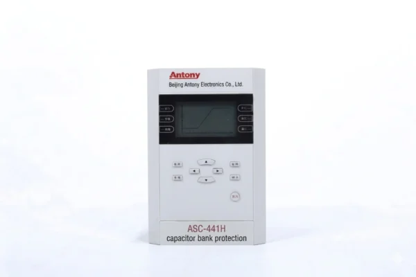
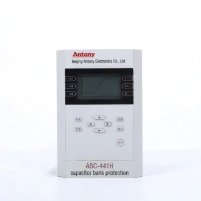
The ASC-441H is a capacitor bank protection relay designed for shunt compensation capacitor banks in medium voltage and low voltage power systems.
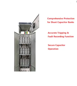
It is suitable for substations, industrial distribution systems and other installations where capacitor banks are used for reactive power compensation and power factor correction.
The relay provides integrated protection, monitoring and communication functions, including unbalance protection, overvoltage, undervoltage, overcurrent and harmonic-related monitoring.
It helps detect capacitor bank abnormalities such as element failure, fuse blowing and phase imbalance, allowing operators to isolate faulty banks before further damage occurs.
Capacitor Bank Protection Relay Functions
| Protection Function |
ANSI Code |
| Three-stage definite time overcurrent protection |
50 / 51 |
| Zero-sequence overcurrent protection |
50N / 51N |
| Zero-sequence overvoltage protection |
59N |
| Overvoltage protection (no-current interlock optional) |
59 |
| Undervoltage protection (current presence interlock optional) |
27 |
| Control circuit disconnection |
74 |
| CT disconnection / Current transformer breakage |
60 |
| Bus PT disconnection / Bus VT failure |
60 |
Communication Mode
- Optional: RS-485, CAN bus, Ethernet,IEC 61850 , IEC 60870-5-103
The ASC-441H records protection operations, fault types, operating parameters and RMS values before and after a fault, helping engineers analyze capacitor bank protection events and identify the cause of operation.
| Item |
Description |
| Event Recording |
Logs protection trips & device faults, including trip type, time and operating parameters |
| Fault Recording Data |
Protection action time, action type, and RMS values before & after trigger |
| Fault Recording Length |
2 cycles before fault, 4 cycles after fault |
| Power-off Data Retention |
48 sets of SOE data, 16 sets of fault reports |
Capacitor Bank Protection Relay Technical Specifications
| Item |
Specification |
| Protection response time |
Average error ≤ 35 ms (including output relay response time) |
| Precision operating range |
0.08 In ~ 20 In |
| Current setting error |
≤ ±2.5% (Current > 1.00 A) |
| Voltage setting error |
≤ ±3% |
| Measurement accuracy (I / U) |
Class 0.2 |
| Measurement accuracy (P / Q) |
Class 0.5 |
| Remote signal resolution |
≤ 2 ms |
Capacitor Bank Protection Relay Applications
| Application |
Protection Focus |
Typical Benefit |
| Substation Capacitor Banks |
Element failure, fuse blowing, phase imbalance |
Protects the bank and maintains stable bus voltage |
| Industrial Power Distribution |
Unbalance, overcurrent |
Prevents equipment damage and production downtime |
| Reactive Power Compensation Systems |
Faulty stages, degraded elements |
Maintains compensation performance |
| Medium-Voltage Capacitor Banks |
Unbalance protection |
Prevents cascading damage from a single element failure |
| Low-Voltage Capacitor Banks |
Overload, overvoltage, undervoltage, unbalance |
Provides protection plus remote monitoring and fault recording |
How Does a Capacitor Bank Protection Relay Work?
Current and Voltage Measurement
The relay samples current and voltage from the capacitor bank through instrument transformers, measuring phase currents, line voltages, unbalance current or voltage, and neutral current where applicable.
Fault Detection
Measured values are compared against configured thresholds to detect element failure, blown fuses, phase imbalance, overvoltage, undervoltage, overcurrent and harmonic distortion. Unbalance protection is key because a failed element changes capacitance distribution and produces a measurable unbalance signal.
Protection Logic
Internal logic distinguishes normal transients from genuine faults using time delays, thresholds and blocking conditions, avoiding nuisance tripping during switching or temporary disturbances.
Trip and Alarm
Minor abnormalities trigger an alarm. Severe faults such as significant unbalance or overcurrent trigger a trip signal to disconnect the capacitor bank. Alarm and trip thresholds are set independently.
Event and Fault Recording
The relay records trip events, alarm events, fault types and measured values at operation, helping engineers identify causes, verify settings and determine whether the issue lies in the capacitor bank, switching device or power system.
Capacitor Bank Protection Relay Settings
| No. |
Display Name |
Range |
Step |
Remarks |
| 1 |
Stage 1 Protection Setting |
|
|
|
| 1.1 |
Stage 1 Protection Enable/Disable |
1/0 |
— |
Stage 1 protection: Enable(1) / Disable(0) |
| 1.2 |
Stage 1 Time Delay |
0.00~120.00s |
0.01s |
|
| 1.3 |
Stage 1 Setting Value |
0.40~99.99A
0.10~20.00A |
0.01A |
In=5A
In=1A |
| 2 |
Stage 2 Protection Setting |
|
|
|
| 2.1 |
Stage 2 Protection Enable/Disable |
1/0 |
— |
Stage 2 protection: Enable(1) / Disable(0) |
| 2.2 |
Stage 2 Time Delay |
0.00~120.00s |
0.01s |
|
| 2.3 |
Stage 2 Setting Value |
0.40~99.99A
0.10~20.00A |
0.01A |
In=5A
In=1A |
| 3 |
Stage 3 Protection Setting |
|
|
|
| 3.1 |
Stage 3 Protection Enable/Disable |
1/0 |
— |
Stage 3 protection: Enable(1) / Disable(0) |
| 3.2 |
Stage 3 Time Delay |
0.00~120.00s |
0.01s |
|
| 3.3 |
Stage 3 Setting Value |
0.40~99.99A
0.10~20.00A |
0.01A |
In=5A
In=1A |
| 4 |
Overvoltage Protection Setting |
|
|
|
| 4.1 |
Overvoltage Protection Enable/Disable |
1/0 |
— |
Overvoltage protection: Enable(1) / Disable(0) |
| 4.2 |
Overvoltage Time Delay |
0.00~120.00s |
0.01s |
|
| 4.3 |
Overvoltage Setting Value |
5.00~120.00V |
0.01V |
|
| 5 |
Undervoltage Protection Setting |
|
|
|
| 5.1 |
Undervoltage Protection Enable/Disable |
1/0 |
— |
Undervoltage protection: Enable(1) / Disable(0) |
| 5.2 |
Undervoltage Time Delay |
0.00~120.00s |
0.01s |
|
| 5.3 |
Undervoltage Setting Value |
5.00~100.00V |
0.01V |
|
| 6 |
Zero-sequence Overcurrent Setting |
|
|
|
| 6.1 |
Zero-sequence Overcurrent Protection |
1/0 |
— |
Zero-sequence overcurrent protection: Enable(1) / Disable(0) |
| 6.2 |
Zero Current Time Delay |
0.00~120.00s |
0.01s |
|
| 6.3 |
Zero Current Setting Value |
0.02~5.00A
0.50~99.00A |
0.01A |
Small current grounding system
380V three-phase four-wire single-phase grounding system |
| 7 |
Zero-sequence Overvoltage Setting |
|
|
|
| 7.1 |
Zero-sequence Overvoltage Protection |
1/0 |
— |
Zero-sequence overvoltage protection: Enable(1) / Disable(0) |
| 7.2 |
Zero Voltage Time Delay |
0.00~120.00s |
0.01s |
|
| 7.3 |
Zero Voltage Setting Value |
0.00~120.00V |
0.01V |
|
| 8 |
Phase-to-Ground Undervoltage Setting |
|
|
|
| 8.1 |
Phase-to-Ground Undervoltage Enable/Disable |
1/0 |
— |
Phase-to-ground undervoltage protection: Enable(1) / Disable(0) |
| 8.2 |
Undervoltage Time Delay |
0.00~120.00s |
0.01s |
|
| 8.3 |
Undervoltage Setting Value |
5.00~70.00V |
0.01V |
|
| 9 |
Phase-to-Ground Overvoltage Setting |
|
|
|
| 9.1 |
Phase-to-Ground Overvoltage Enable/Disable |
1/0 |
— |
Phase-to-ground overvoltage protection: Enable(1) / Disable(0) |
| 9.2 |
Overvoltage Time Delay |
0.00~120.00s |
0.01s |
|
| 9.3 |
Overvoltage Setting Value |
5.00~70.00V |
0.01V |
|
| 10 |
CT Break Setting |
|
|
|
| 10.1 |
CT Break |
1/0 |
— |
CT break alarm: Enable(1) / Disable(0) |
| 10.2 |
CT Break Setting Value |
0.10~5.00A |
0.01A |
|
| 10.3 |
CT Break Time Delay |
1.00~999.99s |
0.01s |
|
| 10.4 |
Load Current Setting Value |
0.05~5.00A |
0.01A |
|
| 11 |
General Setting |
|
|
|
| 11.1 |
Bus PT Break |
1/0 |
— |
Bus PT break detection: Enable(1) / Disable(0) |
| 11.2 |
Control Circuit Break |
1/0 |
— |
Control circuit break: Enable(1) / Disable(0) |
| 11.3 |
Current Blocking Over/Undervoltage |
1/0 |
— |
Current blocking over & undervoltage protection: Enable(1) / Disable(0) |
| 11.4 |
Current Rated 1A |
1/0 |
— |
Enable(1)=1A / Disable(0)=5A |
| 11.5 |
B17 as Maintenance Plate |
1/0 |
— |
B17 maintenance plate: Enable(1) / Disable(0) |
| 11.6 |
Integral Energy Calculation |
1/0 |
— |
Calculate integral energy(1) / Not calculate(0) |
| 11.7 |
Harmonic Component Calculation |
1/0 |
— |
Calculate harmonic component(1) / Not calculate(0) |
| 11.8 |
Current Blocking Value |
0.00~99.99A |
0.01A |
Current blocking setting value |
| 11.9 |
Sudden Change Startup |
0.00~99.99A |
0.01A |
|
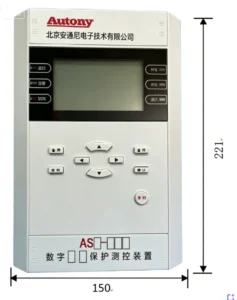
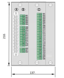
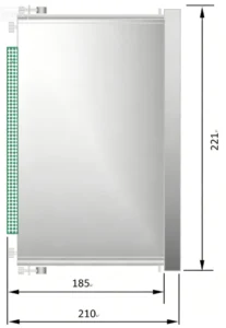
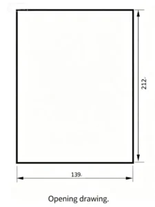
Outline and Installation Dimensions of Capacitor Bank Protection Relay
Why Choose the ASC-441H Capacitor Bank Protection Relay?
| Advantage |
Customer Value |
| Multiple protection functions |
One relay for capacitor bank protection |
| Unbalance protection |
Detect capacitor unit faults |
| Fast protection response |
Rapid fault clearing |
| Flexible settings |
Adapt to different capacitor bank configurations |
| Fault recording |
Easier event analysis |
| Multiple communication options |
Integration with automation systems |
| Factory testing |
Improved commissioning reliability |
| OEM/ODM support |
Adaptation to project requirements |
Capacitor Bank Protection Relay Manufacturer
As a capacitor bank protection relay manufacturer, we provide factory engineering support throughout the project lifecycle.
Our team reviews technical documents, assists with protection configuration, and adapts relay settings to project-specific requirements.
We offer OEM/ODM options for customers who need customized branding or functionality.
Every relay undergoes factory testing before shipment, and we provide commissioning support to ensure correct installation and reliable operation on site.
This combination of product, factory capability and engineering service helps EPC contractors and system integrators reduce risk and shorten project timelines.
FAQ
What Is a Capacitor Bank Protection Relay?
It is a protection device designed for shunt compensation capacitor banks. It monitors current, voltage and unbalance conditions, and provides alarm and trip outputs to isolate faulty banks before further damage occurs.
How Does a Capacitor Bank Protection Relay Work?
It continuously samples current and voltage through instrument transformers. Measured values are compared against configured thresholds. When a fault condition persists beyond the setting delay, the relay issues an alarm or trip signal to disconnect the capacitor bank.
What Protection Functions Does a Capacitor Bank Protection Relay Provide?
Typical functions include unbalance protection, overvoltage, undervoltage, overcurrent, earth fault and harmonic monitoring. Some models also provide over-temperature and switching supervision.
What Is Unbalance Protection in a Capacitor Bank?
Unbalance protection detects changes in capacitance distribution caused by element failure or fuse blowing. It measures unbalance current or unbalance voltage and trips when the level exceeds the setting, preventing voltage stress on remaining elements.
What Faults Can a Capacitor Bank Protection Relay Detect?
It detects capacitor element failure, blown fuses, phase imbalance, overvoltage, undervoltage, overcurrent, earth fault and abnormal harmonic conditions.
Where Are Capacitor Bank Protection Relays Used?
They are used in substations, industrial power distribution systems, reactive power compensation systems, and both medium-voltage and low-voltage capacitor banks.
What Settings Are Required for a Capacitor Bank Protection Relay?
Key settings include unbalance current or voltage threshold, overvoltage and undervoltage levels, overcurrent pickup, time delays, alarm and trip thresholds, and CT/PT ratios.
What Communication Protocols Does the ASC-441H Support?
The ASC-441H supports RS-485 and Modbus communication for remote monitoring, parameter setting and integration with PLC or SCADA systems.


xiao zhang –
This Capacitor Bank Protection Relay (ANSI59/46/51/59N) integrates overvoltage, undervoltage, unbalance and overcurrent protection. Reliable protection logic, flexible parameter setting and multiple communication choices fit reactive power compensation cabinets worldwide.
Jack –
Good compatibility, stable communication — a solid product.