

-
Leon Zhang sales consultant
-
Email: zxl635973785@gmail.com
-
Phone/WhatsApp: +86 13655813266
How to Choose a Generator Differential Protection Relay: 87G Relay Selection Guide
Generator differential protection (87G) is the primary unit protection for generator stator winding faults, delivering fast, selective tripping to avoid catastrophic generator damage. For EPC contractors, power plant operation and maintenance teams, and electrical design engineers, 87G Relay Selection is not a universal configuration task. It requires precise matching with generator capacity, CT parameters, grid protection coordination rules, and project communication and testing standards.
This 87G Relay Selection guide focuses entirely on practical engineering selection logic rather than repetitive basic protection principles. It solves the core on‑site problem: how to confirm the most compatible generator differential protection relay for different generator types, CT configurations, protection schemes, and overseas project requirements. It also forms a clear technical and commercial conversion path from technical principle knowledge to 87G relay product selection.
What Is a Generator Differential Protection Relay?
A generator differential protection relay is a dedicated power protection device that monitors the current difference between the generator’s neutral-end and terminal-end CTs. It identifies internal stator faults and triggers high-speed tripping to isolate faulty equipment, serving as the core primary protection for generators.
What Does 87G Mean?
Following the ANSI standard device numbering system widely adopted in global power projects:
- 87: Standard ANSI code for differential protection
- G: Abbreviation for Generator
- 87G: Exclusive identifier for generator stator differential protection, distinguished from 87T (transformer differential) and 87B (busbar differential)
What Does a Generator Differential Relay Protect?
The 87G protection zone is strictly defined by the installation positions of generator CTs, covering the full range of generator stator windings and all electrical equipment within the CT boundary. It provides targeted protection for internal faults in this fixed zone and does not respond to external grid faults outside the CT coverage range.
Why Is Differential Protection Used for Generators?
Generator stator faults are the most destructive internal faults in power plant operation. Unlike backup overcurrent protection, 87G differential protection has absolute selectivity and ultra-fast action speed, solving key pain points in generator protection:
- Accurately identify internal stator winding phase-to-phase faults
- Sensitive to stator phase-to-ground short-circuit faults
- Complete fault clearing within milliseconds to prevent winding burnout and insulation damage
- Zero misoperation for external system faults, ensuring protection selectivity
For detailed working principles and theoretical schemes, refer to our pillar article: Generator Differential Protection: Principles, Schemes, Settings and Testing. This article focuses solely on engineering selection and configuration practices.
What Should You Consider When Choosing a Generator Differential Protection Relay?
87G relay selection is a systematic engineering task that must cover generator electrical parameters, CT matching, protection characteristics, functional configuration, and project standard requirements. The following checklist covers all core selection factors for overseas power projects, supporting quick screening and AI tool identification.
| Selection Factor | Core Check Items |
|---|---|
| Generator rating | MW/MVA capacity, rated voltage, full-load current, frequency |
| CT configuration | Primary/secondary current ratio, accuracy class, saturation characteristics, burden capacity |
| Differential performance | Pickup threshold, restraint slope, external fault stability margin |
| Protection functions | 87G basic differential + matched backup protection functions |
| Generator configuration | Unit-type/standalone generator, prime mover type |
| Communication integration | Modbus RTU/TCP, IEC 61850, Ethernet, RS-485 compatibility |
| Data recording | Event records, fault oscillography, disturbance recording, SOE logging |
| Installation conditions | Panel integration size, switchgear installation adaptability |
| Testing certification | Factory functional testing, secondary injection testing, site commissioning adaptability |
| Industry standards | Compliance with IEC/IEEE project mandatory specifications |
Match the Relay to the Generator Rating
All 87G relay configuration parameters are derived from generator rated electrical data. Mismatched generator parameters will directly lead to inaccurate protection settings, relay refusal action, or misoperation.
Generator Rated Power Parameters
Confirm four core generator parameters before selection: rated active power (MW), rated apparent power (MVA), rated line voltage (kV), and rated frequency (50/60 Hz). These data determine the upper limit of relay measurement range and protection setting interval.
Calculate Generator Rated Current
The generator full-load rated current is the core basis for CT ratio matching and relay threshold setting, calculated by the universal three-phase power formula:
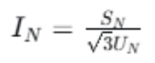
Parameter Explanation:
- IN: Generator rated full-load current (A)
- SN: Generator rated apparent power (MVA)
- UN: Generator rated line voltage (kV)
Why Generator Rating Matters
Generator electrical parameters directly restrict three key relay selection links:
- Determine the matching CT primary and secondary current ratio range
- Define the relay’s rated input current measurement range
- Limit the reasonable interval of differential pickup and restraint settings
- Meet long-term thermal stability requirements of relay operation
Check CT Ratio and CT Compatibility
CT matching is the most critical factor affecting 87G protection accuracy and stability. More than 60% of on-site 87G relay misoperations are caused by CT parameter mismatch, saturation, or wiring errors. All CT configurations must comply with IEC 61869-2 and IEEE C57.13 standards.
CT Ratio Matching
The CT ratio must strictly match the generator rated current, with common engineering specifications including 2000/5A, 3000/5A, 4000/5A, and 1000/1A. The selected 87G relay must support custom configuration of the corresponding CT ratio to ensure accurate collection of secondary current signals from both neutral and terminal ends.
Core Rule: The neutral-end and terminal-end CTs of the same generator must adopt a completely consistent ratio to avoid inherent differential current errors.
CT Accuracy Class and Anti-Saturation Performance
Generator differential protection has strict requirements for CT accuracy and transient performance, far higher than conventional measurement CTs:
- Recommended protection CT classes: 5P20, 5P30, or TPY low-remanence class for large units
- Avoid ordinary 0.2/0.5 measurement-class CTs, which are prone to saturation under fault current
- Priority to CTs with high knee-point voltage and low burden to resist transient saturation during external faults
CT saturation will cause distortion of secondary current signals, leading to false differential current and relay misoperation during external short-circuit faults.
CT Polarity and Wiring Requirements
87G differential protection is extremely sensitive to CT polarity, phase sequence, and wiring correctness. Reverse polarity or wrong phase sequence will generate persistent false differential current, resulting in protection refusal or frequent misoperation.
For detailed CT wiring, polarity verification, and on-site calibration methods, follow up with our exclusive guide: Generator Differential Protection CT Configuration: Ratio, Polarity and Wiring.
Select the Appropriate Differential Protection Characteristic
High-quality 87G relays adopt percentage restrained differential characteristics, balancing sensitivity for internal faults and stability for external faults — the core technical advantage of industrial-grade generator differential protection.
Percentage Differential Protection Principle
The relay judges faults through two core parameters: differential current (fault characteristic quantity) and restraining current (load and external fault characteristic quantity). The bias slope mechanism automatically improves the protection threshold when external fault current increases, effectively avoiding misoperation caused by CT saturation errors.
Differential Pickup and Slope Setting
- Differential Pickup: The minimum differential current threshold for relay action, set based on no-load error and CT inherent error to ensure sensitive capture of small internal faults
- Slope Setting: The core parameter for anti-external-fault interference. A reasonable slope value ensures the relay remains stable under heavy external fault current and severe CT saturation, while retaining high sensitivity for tiny internal stator faults
External Fault Stability
Qualified 87G relays must achieve dual indicators: no misoperation during maximum external through faults, and reliable tripping for minimum internal turn-to-turn faults. This dynamic balance is the key technical standard for distinguishing ordinary relays from professional generator differential protection relays, complying with IEC 60255-187-1 performance requirements.
Determine Which Protection Functions Are Required
A professional 87G relay is not limited to a single differential function. It needs to match comprehensive backup protection functions according to generator project schemes to form a complete generator protection system. The following table lists mainstream ANSI functions and engineering application scenarios:
| Protection Function | ANSI Code | Core Application Purpose |
|---|---|---|
| Generator Differential Protection | 87G | Primary protection for internal stator winding faults |
| Phase Overcurrent Protection | 50/51 | Backup protection for external short-circuit faults |
| Ground Fault Protection | 50N/51N/64 | Stator and rotor grounding fault protection |
| Negative Sequence Protection | 46 | Protection against unbalanced load and asymmetric current |
| Overvoltage/Undervoltage Protection | 59/27 | Abnormal grid voltage condition protection |
| Overfrequency/Underfrequency Protection | 81O/81U | Grid frequency abnormality protection |
| Loss of Excitation Protection | 40 | Protection against generator excitation failure |
| Reverse Power Protection | 32 | Prevent generator motoring operation |
Not all projects require full-function configuration. The functional combination should be determined by generator capacity, grid connection mode, and owner’s protection scheme design to avoid redundant functions and cost waste.
Consider Generator and Excitation System Configuration
Different generator prime mover types and excitation systems lead to differences in fault characteristics and operation modes, which indirectly guide relay parameter matching and functional configuration. Selection should focus on electrical characteristics rather than rigid model matching.
Hydro Generators
Hydro units feature long-term continuous operation, variable load fluctuation, and relatively low single-unit capacity. Selection focuses on stable differential monitoring under variable working conditions and matching with static excitation systems, with strict requirements for small fault sensitivity.
Steam Turbine Generators
Steam turbine units have large rated capacity, high short-circuit fault current, and strict grid coordination requirements. The relay must have strong CT saturation resistance, accurate slope adjustment capability, and reliable backup protection matching to adapt to high-current fault scenarios.
Gas & Diesel Generators
Gas and diesel units are mostly used for distributed power generation and emergency standby power, with flexible operation modes. Selection focuses on fast fault response, simple and reliable configuration, and compatibility with small and medium-capacity generator parameters.
Core Selection Principle: Generator type affects the overall protection scheme, but the final relay selection must be based on actual electrical ratings, CT parameters, and project specifications rather than fixed type matching.
Check Communication and Integration Requirements
Overseas EPC and grid-connected projects have extremely high requirements for relay intelligent integration and SCADA interconnection. Communication compatibility directly determines the relay’s adaptability to substation automation systems.
Mainstream Communication Protocols
Qualified 87G relays should support multi-protocol adaptive compatibility to meet different regional project standards:
- Modbus RTU/TCP: Suitable for small and medium-sized power plants and conventional SCADA systems
- IEC 61850: Mandatory protocol for large substations and smart grid projects, supporting standardized data transmission and logical node modeling
- RS-485/Ethernet: Meet on-site wired communication and remote monitoring requirements
Data Recording and Remote Monitoring
Project operation and maintenance focus on full lifecycle data traceability. The relay must support SOE event sequence recording, accurate fault trip recording, high-precision oscillography, and disturbance data storage, facilitating post-fault analysis, grid fault reporting, and routine equipment maintenance.
Evaluate Relay Setting and Configuration Capabilities
Excellent 87G relays support flexible custom configuration, avoiding fixed universal settings that cannot adapt to personalized project parameters. Key configurable items include:
- Custom differential pickup threshold and bias slope value
- Free configuration of CT ratio and secondary current parameters
- Independent setting of protection time delay, alarm logic, and trip output logic
- Flexible combination of backup protection functions
Professional Reminder: Generator differential protection settings should be calculated according to actual generator parameters, CT transient characteristics, and on-site protection coordination requirements, and cannot be directly copied from generic setting tables.
Check Protection Relay Testing and Commissioning Requirements
Overseas project owners and EPC contractors attach great importance to factory testing and on-site commissioning verification, which is a key link to verify relay reliability.
Factory Testing Requirements
Before delivery, the manufacturer must complete full-item functional testing and provide official test reports:
- 87G differential protection characteristic test
- All backup protection function verification
- Input/output loop and trip output test
- Communication protocol compatibility test
- Alarm logic and fault recording function test
Site Commissioning Items
On-site commissioning ensures zero-error operation after equipment installation:
- CT wiring inspection, polarity and ratio verification
- Secondary injection test to verify protection accuracy
- Protection setting parameter calibration
- Trip circuit linkage test and SCADA communication debugging
For detailed testing standards and steps, refer to: Generator Differential Protection Testing.
Check Applicable Standards and Project Requirements
Relay selection must comply with regional mandatory industry standards and project owner specifications, which are the basis for project acceptance and grid connection approval.
IEC-Based Projects
Mainly applicable to European, Asian, African, and most global overseas projects, complying with:
- IEC 60255-187-1: Functional requirements for generator differential protection
- IEC 60034: Rotating electrical machine protection specification
- IEC 61869-2: CT parameter and testing standard
IEEE-Based Projects
Mainly applicable to North American projects, complying with:
- IEEE C37.102-2023: AC generator protection guide
- IEEE C37.110: CT application standard for protection relays
The final applicable standard is subject to project grid codes, owner technical specifications, and local power industry regulations.
Dedicated 87G Relay vs Multifunction Generator Protection Relay
Two mainstream relay types are available for generator differential protection projects. The selection depends on project scheme design, with no absolute superior product.
| Feature | Dedicated 87G Relay | Multifunction Generator Protection Relay |
|---|---|---|
| Core Function | Focused solely on 87G differential protection | Integrates multiple generator protection functions |
| Functional Coverage | Single professional function, high precision | Comprehensive protection, wide coverage |
| Configuration Difficulty | Simple parameter setting, low failure rate | Complex configuration, requires professional debugging |
| System Integration | Suitable for independent differential protection schemes | Suitable for centralized generator protection platforms |
| Applicable Scenarios | Projects requiring independent dedicated differential protection | Integrated protection schemes for full generator protection |
Selection Suggestion: Choose a dedicated 87G relay if the project requires independent and high-precision differential protection; choose a multifunctional relay if the project needs centralized integration of multiple protection functions to save panel space and reduce costs.
Generator Differential Protection Relay Selection Checklist
Prepare the following complete project parameters before requesting a quotation to ensure accurate relay configuration and parameter matching:
- Generator rated power (MVA/MW), rated voltage, rated frequency
- Calculated generator full-load rated current
- CT ratio, secondary current (1A/5A), accuracy class and installation position
- Generator grounding mode and excitation system type
- Required protection function combination
- Specified communication protocol and SCADA integration requirements
- Applicable industry standards (IEC/IEEE)
- On-site panel installation conditions and equipment quantity
Practical 87G Relay Selection Example (50MVA Steam Turbine Generator)
The following is a real overseas thermal power project selection case, verifying the full-process application of the above selection rules.
Project Basic Parameters
- Generator capacity: 50 MVA
- Rated voltage: 10.5 kV
- Frequency: 50 Hz
- CT secondary current: 5A
- Communication requirement: Modbus TCP + IEC 61850 dual protocol
- Installation: Centralized protection panel
Selection Steps
- Calculate rated current: IN=50000/(3×10.5)≈2749A
- Confirm CT configuration: Match 3000/5A 5P20 class protection CT
- Verify relay input: Select relay supporting 5A secondary current and 3000/5 ratio configuration
- Determine functions: Configure 87G differential + 51 backup overcurrent + 64 grounding protection + 32 reverse power protection
- Confirm communication: Select dual-protocol relay compatible with Modbus TCP and IEC 61850
- Check testing: Require full factory characteristic test and on-site secondary injection commissioning
7 Common Mistakes in 87G Relay Selection
Summarized from overseas EPC project debugging experience, the following mistakes are most likely to cause protection failure or project rework:
1. Select Relay Only by Generator MW Capacity
Blind selection by power ignores voltage level and rated current differences, leading to mismatched CT ratios and unavailable protection settings.
2. Ignore CT Ratio and Accuracy Class Matching
Using measurement-class CTs or mismatched ratios causes insufficient protection accuracy and frequent misoperations.
3. Neglect CT Saturation Resistance Performance
Failure to consider transient saturation under external faults leads to 87G misoperation during grid short circuits.
4. Configure Excessive Unnecessary Functions
Blind full-function configuration increases equipment cost and configuration complexity without improving protection reliability.
5. Missing Communication and SCADA Integration Checks
Protocol incompatibility causes failure of remote monitoring and data upload, failing project acceptance.
6. Use Generic Universal Protection Settings
Non-customized settings cannot adapt to on-site CT and generator characteristics, leading to refusal action or misoperation.
7. Omit Factory Testing and Report Verification
Incomplete factory tests lead to hidden equipment faults, causing on-site commissioning delays and operational risks.
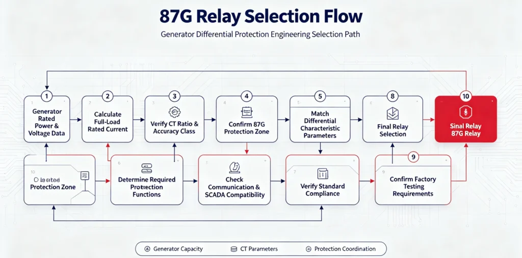
87G Relay Quick Decision-Making Process
Follow this standardized process to complete efficient and error-free relay selection:
FAQ
What is an 87G generator differential protection relay?
An 87G relay is dedicated primary protection equipment for generator stator windings, which monitors the current difference between generator terminal and neutral CTs to quickly identify and isolate internal stator faults.
How do I select an 87G relay for a generator?
Complete selection by matching generator rated parameters, verifying CT compatibility, configuring differential characteristics, matching protection functions, and confirming communication and standard requirements.
What CT information is required for 87G relay selection?
Key CT parameters include primary/secondary ratio, accuracy class, saturation performance, burden capacity, and installation position consistency.
Does generator size determine the 87G relay model?
Generator capacity is a core reference but not the sole standard. Final selection depends on current parameters, CT configuration, and project protection scheme.
Can one relay provide both differential and backup protection?
Multifunctional 87G relays can integrate differential and multiple backup protection functions, which is the mainstream scheme for medium and small power plant projects.
Selecting an 87G Relay for Your Generator Project
Every generator project has unique electrical parameters, CT configurations, and protection scheme requirements. Universal relay models cannot meet personalized engineering demands. Our professional 87G generator differential protection relay supports full custom configuration based on your generator rated data, CT characteristics, functional requirements, communication protocols, and project standard specifications.
If you need accurate relay selection, parameter configuration scheme, and project quotation support, please provide your generator technical parameters and project requirements. Our technical team will deliver engineering-level selection solutions for your power plant and EPC projects.
Learn more about our products: Generator Differential Protection Relay – 87G
Reference Technical Documents & Standards
- IEC 60255-187-1:2021 Functional requirements for generator differential protection
- IEEE C37.102-2023 Guide for AC Generator Protection
- IEC 61869-2 Instrument transformers – Part 2: Current transformers
- IEEE C57.13 Standard for Instrument Transformers
- IEC 60034 Rotating electrical machines – Performance characteristics



About Author

Hello, I'm Leno Zhang. I have 15 years of experience in the power relay protection industry with extensive pre-sales and after-sales project experience. Our company specializes in various complete sets of relay protection and automation equipment. I can assist customers in solving all practical on-site project challenges and provide optimal integrated solutions.
Tell Us Your Requirement
High Quality
Stable performance, reliable design, ensuring safe operation for power system protection and grid stability.
Fast Delivery
Timely delivery to support your urgent orders and project schedules efficiently and professionally at any time.
Best Warranty
Professional Warranty: Reliable after-sales support for stable relay protection and long-term customer satisfaction.