

-
Leon Zhang sales consultant
-
Email: zxl635973785@gmail.com
-
Phone/WhatsApp: +86 13655813266
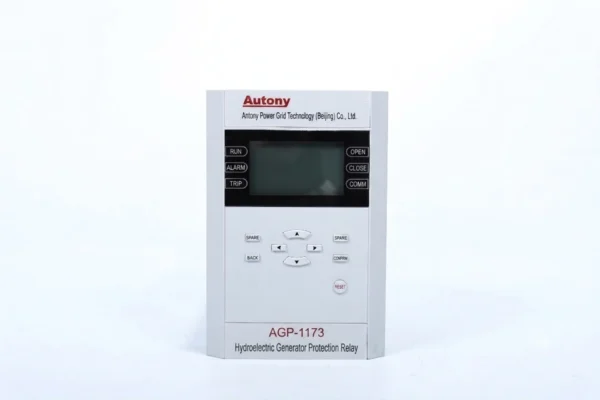
400V Low Voltage Hydroelectric Generator Protection Relay
This small hydro unit control system based on our device features automatic startup, excitation, regulation, synchronization, power adjustment, normal & emergency shutdown, and multi-protection for voltage, current, frequency and temperature.
Send your requirements, we will quote for you within 12 hours
Description
Overview of Hydroelectric Generator Protection Relay
The 400V Low Voltage Hydroelectric Generator Protection Relay is an integrated protection and control device designed for small hydropower units with a generator outlet voltage of 400V and a single-unit capacity below 1000 kW. It combines generator protection, automatic startup and shutdown, synchronization, speed regulation, water-level control and fault recording in one device.
Key Specifications
| Item | Specification |
|---|---|
| Generator Voltage | 400V |
| Unit Capacity | <1000 kW |
| Application | Small hydropower |
| Protection | Overcurrent, voltage, frequency, reverse power, earth fault |
| Control | Startup / shutdown / speed regulation |
| Synchronization | Generator synchronization |
| Water Control | Water-level startup/shutdown/regulation |
| Recording | Fault waveform recording |
Integrated Hydroelectric Generator Protection and Control
Unlike a standalone protection relay, this device combines electrical protection with key small-hydropower unit control functions, reducing the need for multiple separate control and protection devices.
Product Positioning
This all-in-one intelligent hydroelectric unit protection and control device integrates complete multi-functions including fault protection, unit speed regulation, generator synchronizing and water level regulation.
As a professional hydroelectric generator protection relay , it serves as an ideal small hydropower plant protection device and an optimal hydropower retrofit relay for upgrading outdated control systems of mini hydropower stations.
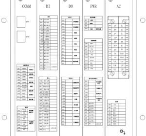
Function of Hydroelectric Generator Protection Relay
Unit Control Functions
- One-button startup and one-button shutdown
- Water level startup, water level shutdown, water level power regulation
- Unit synchronizing function
- Unit speed regulation function
- Control of other external electric equipment of the unit
Main Protection Functions
- Three-stage phase overcurrent protection
- Inverse-time phase overcurrent protection
- Negative-sequence overcurrent protection
- Zero-sequence overcurrent protection
- Reverse power protection
- Overload protection
- Frequency protection
- Voltage protection
- Non-electrical quantity protection
- Control circuit breakage alarm
- PT circuit breakage alarm
- Fault waveform recording
Generator Protection Relay setting calculation xls
| No. | Setting Name | Setting Range | Unit | Parameter Description |
|---|---|---|---|---|
| 1 | Instantaneous Overcurrent | 0.1-100 | A | Set according to actual conditions, this setting is for printing only |
| 2 | Time-Delayed Instantaneous Overcurrent | 0.1-100 | A | Default as Zone 1 |
| 3 | Time-Delayed Instantaneous Overcurrent Time Delay | 0~100 | S | – |
| 4 | Phase Overcurrent | 0.1-100 | A | – |
| 5 | Phase Overcurrent Time Delay | 0~100 | S | – |
| 6 | Low Voltage Blocking | 1~400 | V | – |
| 7 | Negative Voltage Blocking | 1~400 | V | – |
| 8 | Inverse Time Phase Overcurrent | 0.1-100 | A | – |
| 9 | Inverse Time Phase Overcurrent Time Delay | 0~100 | S | – |
| 10 | Inverse Time Phase Overcurrent Type | 0~3 | – | 0=Disabled, 1=Normal Inverse, 2=Very Inverse, 3=Extremely Inverse |
| 11 | Overload | 0.1-100 | A | – |
| 12 | Overload Time Delay | 0~100 | S | – |
| 13 | Overload Type | 0~2 | – | 0=Disabled, 1=Trip, 2=Alarm |
| 14 | Zero-Sequence Overcurrent Stage I | 0.1-100 | A | – |
| 15 | Zero-Sequence Overcurrent Stage I Time Delay | 0~100 | S | – |
| 16 | Zero-Sequence Overcurrent Stage II | 0.1-100 | A | – |
| 17 | Zero-Sequence Overcurrent Stage II Time Delay | 0~100 | S | – |
| 18 | Zero-Sequence Overcurrent Stage III | 0.1-100 | A | – |
| 19 | Zero-Sequence Overcurrent Stage III Time Delay | 0~100 | S | – |
| 20 | Zero-Sequence Overcurrent Stage III Type | 0~2 | – | 0=Disabled, 1=Trip, 2=Alarm |
| 21 | Zero-Sequence Voltage Blocking Setting | 1~400 | V | – |
| 22 | Negative-Sequence Overcurrent Stage I | 0.1-100 | A | – |
| 23 | Negative-Sequence Overcurrent Stage I Time Delay | 0~100 | S | – |
| 24 | Negative-Sequence Overcurrent Stage II | 0.1-100 | A | – |
| 25 | Negative-Sequence Overcurrent Stage II Time Delay | 0~100 | S | – |
| 26 | Negative-Sequence Overcurrent Stage II Type | 0~2 | – | 0=Disabled, 1=Trip, 2=Alarm |
| 27 | Reverse Power Protection Setting | 0.10~900.00 | W | Reverse power protection setting, set with secondary value |
| 28 | Reverse Power Protection Time Delay | 0~100 | S | – |
| 29 | Overvoltage Setting | 1~600 | V | – |
| 30 | Overvoltage Time Delay | 0~100 | S | – |
| 31 | Undervoltage Setting | 1~400 | V | – |
| 32 | Undervoltage Time Delay | 0~100 | S | – |
| 33 | Zero-Sequence Overvoltage Setting | 1~400 | V | – |
| 34 | Zero-Sequence Overvoltage Time Delay | 0~100 | S | – |
| 35 | Zero-Sequence Overvoltage Type | 0~2 | – | 0=Disabled, 1=Trip, 2=Alarm |
| 36 | Underfrequency Protection Setting | 35~65 | Hz | – |
| 37 | Underfrequency Protection Time Delay | 0~100 | S | – |
| 38 | Low Voltage Blocking Underfrequency Setting | 1~400 | V | – |
| 39 | Slip Frequency Blocking Underfrequency Setting | 1~30 | Hz/s | – |
| 40 | Overfrequency Protection Setting | 35~65 | Hz | – |
| 41 | Overfrequency Protection Time Delay | 0~100 | S | – |
| 42 | PT Circuit Breakage Time Delay | 0~100 | S | – |
| 43 | Control Circuit Breakage Time Delay | 0~100 | S | – |
| 44 | Non-Electrical Quantity 1 Time Delay | 0~100 | S | – |
| 45 | Non-Electrical Quantity 2 Time Delay | 0~100 | S | – |
| 46 | Non-Electrical Quantity 3 Time Delay | 0~100 | S | – |
| 47 | Non-Electrical Quantity 4 Time Delay | 0~100 | S | – |
| 48 | DC Channel 1 Lower Conversion Limit | 0-600 | – | Transmitter calculation value, this setting corresponds to 4mA |
| 49 | DC Channel 1 Upper Conversion Limit | 0-600 | – | Transmitter calculation value, this setting corresponds to 20mA |
| 50 | DC Channel 2 Lower Conversion Limit | 0-600 | – | – |
| 51 | DC Channel 2 Upper Conversion Limit | 0-600 | – | – |
| 52 | DC Channel 3 Lower Conversion Limit | 0-600 | – | – |
| 53 | DC Channel 3 Upper Conversion Limit | 0-600 | – | – |
FAQ
Q: What units is the 400V low voltage hydroelectric generator protection relay suitable for?
A: This 400V hydroelectric generator protection relay applies to mini hydropower generating units with outlet voltage 400V and single unit capacity below 1000kW, widely used in small rural hydropower stations.
Q: What integrated functions does the 400V low voltage hydroelectric generator protection relay have?
A: Our 400V hydroelectric generator protection relay is an all-in-one control device, combining generator fault protection, speed regulation, unit synchronizing and water level power control functions.
Q: Does this 400V low voltage hydroelectric generator protection relay support rotor earth fault protection (ANSI 64R)?
A: Yes. The 400V hydroelectric generator protection relay is equipped with voltage injection type 64R rotor earth fault protection, which is the core protection for hydro generators.
Q: What protection functions are built into the 400V low voltage hydroelectric generator protection relay?
A: This hydroelectric generator protection relay covers three-stage phase overcurrent, reverse power, negative-sequence overcurrent, zero-sequence overcurrent, over/under frequency, PT break alarm, multi-channel non-electrical quantity protection and fault waveform recording.
Other Generator Protection Equipment
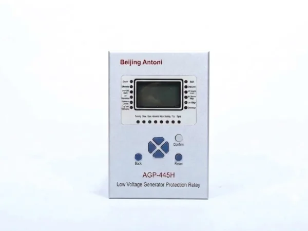
400V Low Voltage Generator Protection Relay
64R Rotor Earth Fault Protection Relay
5 reviews for 400V Low Voltage Hydroelectric Generator Protection Relay
Related products
High Quality
Stable performance, reliable design, ensuring safe operation for power system protection and grid stability.
Fast Delivery
Timely delivery to support your urgent orders and project schedules efficiently and professionally at any time.
Best Warranty
Professional Warranty: Reliable after-sales support for stable relay protection and long-term customer satisfaction.
Jack –
This equipment integrates abundant functions. A single unit can fully meet the operation demands of small hydropower stations, which not only cuts costs but also saves installation space.
Jack –
The product is equipped with comprehensive functions and stable performance, which can meet the operation requirements of small hydropower stations.
Jack –
The product is excellent and trustworthy.
Jack –
The product is fully featured and meets all usage requirements.
blake –
good job