

-
Leon Zhang sales consultant
-
Email: zxl635973785@gmail.com
-
Phone/WhatsApp: +86 13655813266
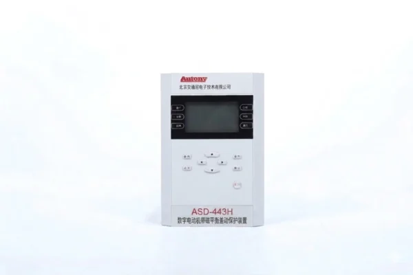
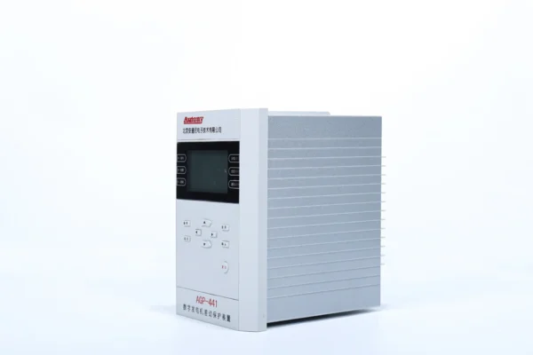
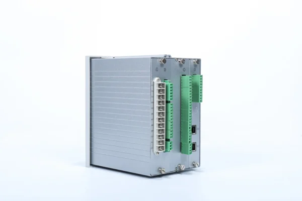
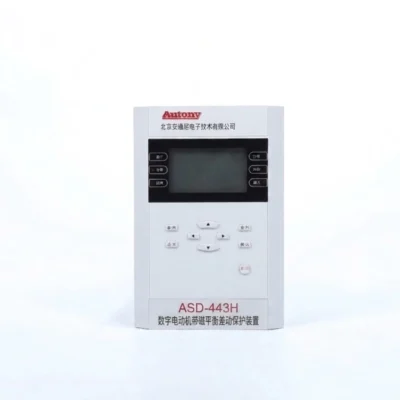
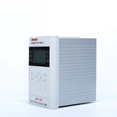
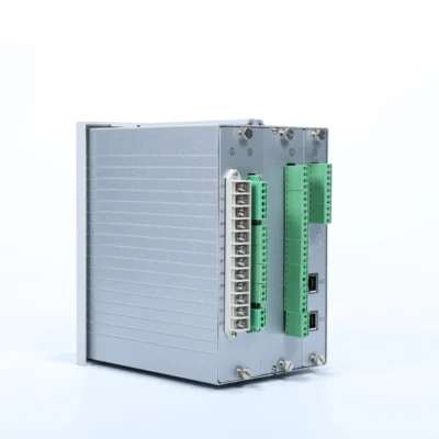
Motor Self-Balancing Differential Protection Relay
For motors adopting self‑balancing differential protection schemes, medium‑voltage motor differential protection and the self‑balancing differential protection function of the Motor Self‑Balancing Differential Protection Relay must be properly configured; this device is applicable to the protection and monitoring of both high‑voltage and low‑voltage asynchronous motors.
Protection Configuration(ANSI)
27/46/48/49/50/51/50N/51N/51LR/59/59N/60/63/81O/81U/87M
Communication Mode
Optional: RS-485, CAN bus, Ethernet, IEC 60870-5-103 (IEC-103), IEC 61850
Send your requirements, we will quote for you within 12 hours
Description
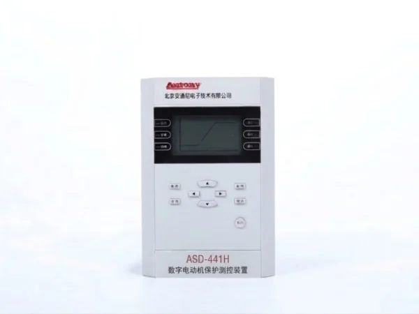
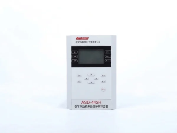
The 443H is a motor self-balancing differential protection relay designed for the protection and monitoring of high-voltage and low-voltage asynchronous motors. It uses a self-balancing differential protection scheme to detect internal motor faults with high sensitivity. The relay integrates ANSI 87M differential protection with overcurrent, overload, stall, negative-sequence, earth-fault, voltage and frequency protection functions.
Overview of Motor Self-Balancing Differential Protection Relay
A motor self‑balancing differential protection relay provides sensitive protection against internal motor faults by using a self‑balancing differential protection scheme. The 443H motor protection relay combines differential protection with motor protection, measurement, control and communication functions.
Key Features
- ANSI 87M self-balancing differential protection
- Magnetic balance differential protection
- Reduced CT wiring requirements
- High sensitivity to internal motor faults
- Overcurrent and overload protection
- Negative-sequence protection
- Earth fault protection
- Stall and long-start protection
- Voltage and frequency protection
- Event recording and communication
What Is a Motor Self-Balancing Differential Protection Relay?
Definition
A motor self-balancing differential protection relay is a protection device that compares currents at both ends of a motor winding to detect internal faults. It uses a self-balancing principle, meaning the relay does not require external matching transformers or complex settings to balance the current ratio between the two sides.
How the Self-Balancing Principle Works
In conventional motor differential protection, current transformers on both sides of the winding must be matched in ratio and connected with correct polarity. Any mismatch causes false differential current. A self-balancing relay handles this internally, automatically compensating for ratio and phase differences. This simplifies installation, reduces wiring errors and improves sensitivity to genuine internal faults.
What Motor Faults It Detects
It detects internal faults such as turn-to-turn short circuits, phase-to-phase faults, winding-to-ground faults and internal insulation breakdown. These faults may not be picked up by overload or negative-sequence protection at an early stage, so differential protection provides faster and more selective tripping.
How Does Motor Self-Balancing Differential Protection Work?
Normal Motor Operation
Under normal conditions, the current entering one end of the motor winding equals the current leaving the other end. The self-balancing circuit sees these two currents as equal and opposite, so the net differential current is essentially zero. The relay remains stable and does not trip.
External Fault Conditions
When a fault occurs outside the protected zone, such as a downstream short circuit or a system disturbance, current still passes through the motor winding without escaping it. Both sides see the same current, so the differential quantity stays balanced. The self-balancing design automatically compensates for CT ratio and phase differences, preventing false operation caused by normal system imbalance or external faults.
Internal Motor Fault
When a fault occurs inside the motor winding, such as a turn-to-turn short, phase-to-phase fault or insulation breakdown, part of the current no longer flows through both ends equally. This breaks the balance and produces a differential current. Once this differential current exceeds the setting threshold, the relay trips the circuit breaker to isolate the motor and limit damage.
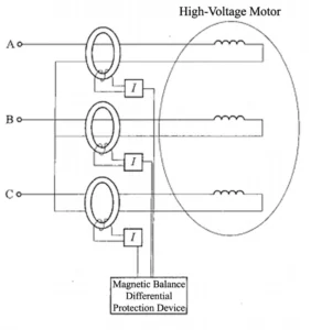
Motor Differential Protection diagram
Self-Balancing vs Conventional Motor Differential Protection
| Item | Self-Balancing Differential | Conventional Longitudinal Differential |
|---|---|---|
| Protection Principle | Magnetic balance | Current comparison |
| CT Arrangement | Special balanced CT arrangement | CTs on both sides |
| Secondary Wiring | Reduced in suitable schemes | More extensive |
| CT Quantity | Can be reduced | Usually more CTs required |
| Installation | Simpler for compatible motors | More complex |
| Internal Fault Sensitivity | High when correctly configured | High |
| Application | Motors designed for self-balancing scheme | Motors with conventional differential scheme |
For the applicable motor configuration, the scheme can use one balanced window CT per phase, reducing the CT and secondary wiring requirements compared with conventional arrangements.
Motor Self-Balancing Differential Protection Relay Functions
1. Self-Balancing Differential Protection — ANSI 87M
87M Self-Balancing Differential Protection
2. Current Protection
- 50/51 Overcurrent
- 50N/51N Zero-Sequence Overcurrent
- 46 Negative-Sequence Overcurrent
- 51LR Stall Protection
3. Thermal & Starting Protection
- 49 Thermal Overload
- 48 Long Start-Up Protection
- Motor Start Blocking
4. Voltage & Frequency Protection
- 27 Undervoltage
- 59 Overvoltage
- 59N Zero-Sequence Overvoltage
- 81U Underfrequency
- 81O Overfrequency
5. Supervision & Non-Electrical Protection
- 60 PT Circuit Supervision
- 63 Non-Electrical Protection
- Control Circuit Supervision
Motor Voltage and Application Range
| Motor Type | Typical Application |
|---|---|
| Medium-Voltage Motors | 3kV / 6kV / 10kV |
| High-Voltage Motors | Project-specific |
| Low-Voltage Motors | Compatible configurations |
Communication and Time Synchronization
| Interface | Protocol / Function |
|---|---|
| Ethernet | IEC 60870-5-103 / IEC 61850 |
| RS-485 | Modbus RTU |
| Time Synchronization | SNTP / IRIG-B |
Motor Self-Balancing Differential Protection Relay Settings
| Setting | Range |
|---|---|
| Motor Rated Current | 0.1–100 A |
| 87M Magnetic Balance Differential | 0.1–100 A |
| Motor Start-Up Time | 0–600 s |
| Overcurrent | 0.1–100 A |
| Negative-Sequence Current | 0.1–100 A |
| Zero-Sequence Current | 0.1–100 A |
| Overvoltage | 1–600 V |
| Undervoltage | 1–400 V |
CT Configuration for Self-Balancing Motor Differential Protection
In a self-balancing motor differential protection scheme, the CT arrangement is the core of how the relay senses internal faults. The most common configuration uses a three-window CT scheme: the line-side conductor, the neutral-side conductor and a magnetic balance path all pass through the same CT core. The line-side and neutral-side currents flow in opposite directions under normal conditions, so their magnetic effects cancel each other. The relay sees no differential current and remains stable.
When an internal fault occurs, the balance is broken. Part of the current escapes through the fault path instead of returning through the neutral-side conductor. The magnetic cancellation no longer holds, and a differential current appears in the CT secondary circuit. Once this differential current exceeds the threshold, the relay trips. This arrangement avoids the need for matched CT ratios and complex polarity wiring, which is the key advantage of the self-balancing principle.
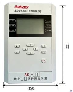
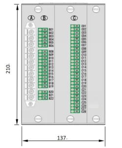
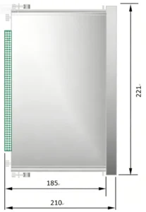
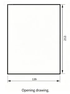
Outline and Installation Dimensions
FAQ
What Is a Motor Self-Balancing Differential Protection Relay?
It is a protection device that compares currents at both ends of a motor winding to detect internal faults. Unlike conventional differential protection, it uses a self-balancing principle that automatically compensates for CT ratio and phase differences, eliminating the need for external matching transformers and complex polarity wiring.
How Does Motor Self-Balancing Differential Protection Work?
Under normal operation, the current entering one end of the winding equals the current leaving the other end, so the net differential current is zero. When an internal fault occurs, part of the current escapes through the fault path, breaking the balance and producing a differential current. Once this exceeds the threshold, the relay trips.
What Is the Difference Between Self-Balancing and Conventional Motor Differential Protection?
Conventional differential protection requires carefully matched CT ratios and correct polarity wiring between the two sides of the motor winding. Any mismatch can cause false differential current and nuisance tripping. Self-balancing protection handles ratio and phase compensation internally, simplifying installation and improving sensitivity to genuine internal faults.
How Many CTs Are Required for Self-Balancing Motor Differential Protection?
In a typical three-window CT scheme, the line-side conductor, neutral-side conductor and magnetic balance path all pass through a single CT core. This arrangement avoids the need for two separate matched CTs and complex secondary wiring, reducing installation cost and error risk.
What Motor Faults Can Self-Balancing Differential Protection Detect?
It detects turn-to-turn short circuits, phase-to-phase faults, winding-to-ground faults and internal insulation breakdown. These faults may not be picked up by overload or negative-sequence protection at an early stage, so differential protection provides faster and more selective tripping.
What Motors Is the 443H Protection Relay Suitable For?
The 443H relay is suitable for low-voltage three-phase AC motors in industrial facilities, motor control centers, water treatment systems, pumping stations, fans, compressors and conveyors. It is designed for motors where internal fault protection and continuous monitoring are required.
What Other Protection Functions Are Integrated Into the Relay?
In addition to self-balancing differential protection, the relay integrates overload, phase loss, phase imbalance, locked rotor, undercurrent, overcurrent, earth fault and temperature-related protection. It also provides measurement, fault recording and communication functions for remote monitoring.
How Is the Motor Self-Balancing Differential Protection Relay Set and Commissioned?
Commissioning typically includes visual inspection, CT wiring verification, differential current balance check, alarm and trip threshold setting, and functional trip test. The self-balancing design reduces the need for complex ratio matching, but correct CT installation and polarity orientation must still be confirmed before energization.
Associated Products
2 reviews for Motor Self-Balancing Differential Protection Relay
Related products
High Quality
Stable performance, reliable design, ensuring safe operation for power system protection and grid stability.
Fast Delivery
Timely delivery to support your urgent orders and project schedules efficiently and professionally at any time.
Best Warranty
Professional Warranty: Reliable after-sales support for stable relay protection and long-term customer satisfaction.
xiao zhang –
Self-balancing (magnetic balance) differential relay (ANSI 87M) is the primary internal fault protection for medium & high voltage critical motors ≥3kV/200kW. Each phase adopts single toroidal window CT: motor line-side lead and neutral-side lead pass oppositely through one same CT core, flux counteracts under normal load, no secondary output. Instant trip for stator phase short, winding ground & inter-turn fault with ultrahigh sensitivity, simpler wiring vs conventional split CT longitudinal differential.
Jack –
Time-stamped fault records help pinpoint root causes accurately.