-
Leon Zhang sales consultant
-
Email: zxl635973785@gmail.com
-
Phone/WhatsApp: +86 13655813266


ATN-400 Transformer protection panel
The transformer protection panel is a comprehensive protection, measurement and control cabinet specially configured for the main transformer. It is generally installed in the high‑voltage distribution room.
The standard cabinet dimension is 800×600×2260 mm, and non‑standard customized sizes are available according to site special requirements.
Communication Mode:Optional: RS-485, CAN bus, Ethernet, IEC 60870-5-103 (IEC-103)
In-house Factory & Technical Team, OEM ODM Custom Electrical Equipment
Send your requirements, we will quote for you within 12 hours
Description
Overview of Transformer protection panel
- The transformer protection panel is a comprehensive protection, measurement and control cabinet specially configured for the main transformer. It is generally installed in the high‑voltage distribution room.
-
The standard cabinet dimension is 800×600×2260 mm, and non‑standard customized sizes are available according to site special requirements.
-
The internal device configuration is flexible and fully determined by the actual project design drawings and technical specifications.
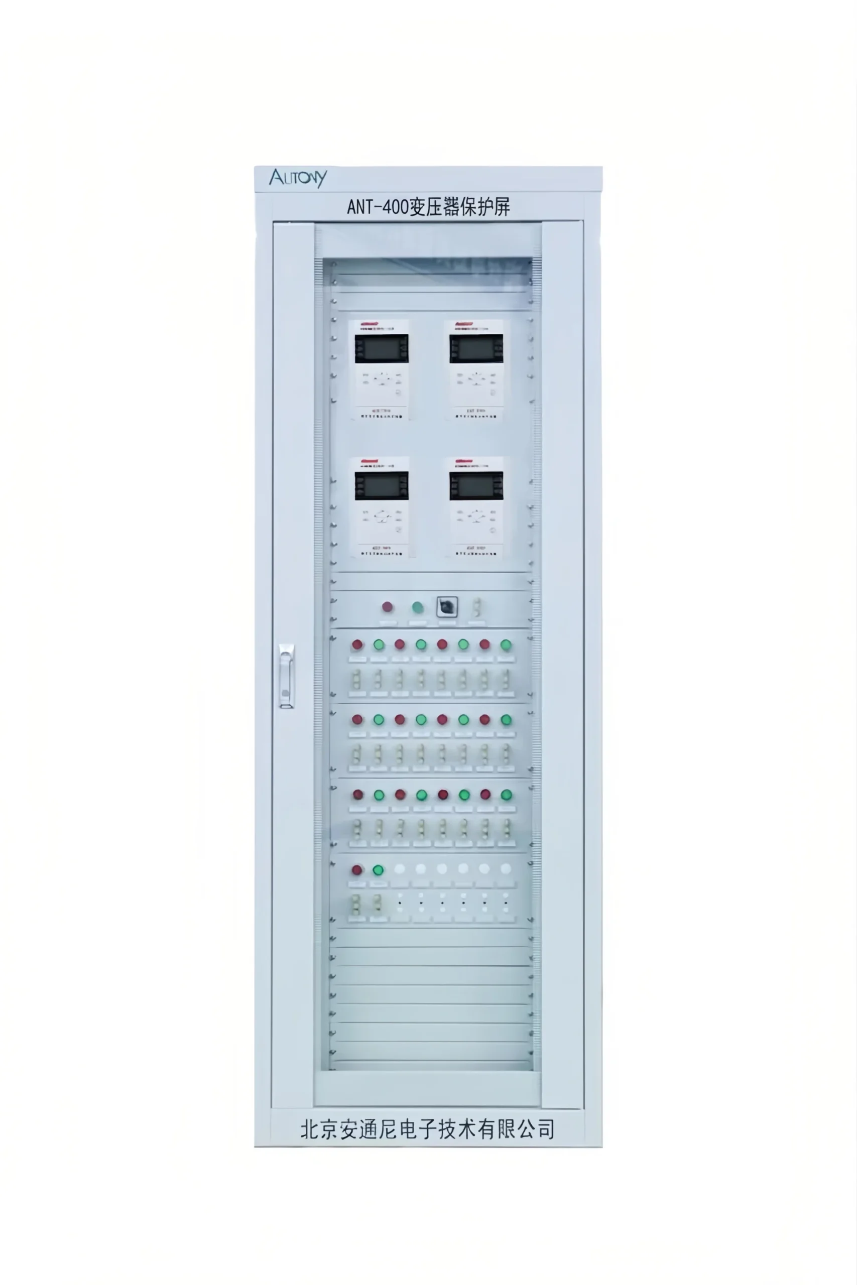
Main Equipment Composition
The main secondary equipment inside the cabinet includes:
- transformer differential protection device
- transformer backup protection device
- transformer non‑electrical quantity protection device
- transformer measurement and control device.
- Auxiliary supporting equipment includes transformer temperature controller and on‑load tap changer controller.
Function Description of Each Component
Transformer Differential Protection Device
- It serves as the main internal fault protection for the transformer, dedicated to detecting internal short circuits and winding turn‑to‑turn faults.
- Core functions include differential instantaneous overcurrent protection, restrained differential protection, second‑harmonic blocking logic, differential current alarm and CT abnormality detection.
- It trips rapidly to isolate severe internal transformer faults with high sensitivity and reliability.
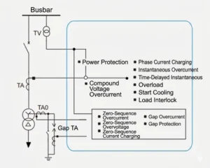
Transformer Backup Protection Device
- It includes high‑voltage side backup protection and low‑voltage side backup protection. For three‑winding transformers, medium‑voltage side backup protection is additionally equipped.
- The protection scope covers transformer bushings, outgoing lines and external busbar areas.
- It also acts as remote and local backup protection when differential protection fails or is out of service for maintenance.
| No. | Protection Function |
|---|---|
| 1 | Composite voltage (undervoltage + negative sequence voltage) restrained overcurrent protection |
| 2 | Zero‑sequence overcurrent protection & zero‑sequence overvoltage protection |
| 3 | Overload protection and overload blocking |
| 4 | Undervoltage protection and under‑frequency load shedding protection |
| 5 | Inverse‑time overcurrent protection |
| 6 | Three‑phase current unbalance protection |
| 7 | PT broken line detection and busbar insulation monitoring |
| 8 | Trip output logic and control circuit disconnection monitoring |
| 9 | CT broken line detection and blocking logic |
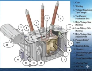
Transformer Non‑Electrical Quantity Protection Device
- Specially designed for oil‑immersed power transformers, it collects non‑electrical signals such as gas accumulation, pressure and oil temperature inside the transformer.
- It provides reliable early warning and tripping against internal insulation degradation, internal arcing, overheating and sudden pressure rise.
- Main functions: heavy gas trip, light gas alarm, high oil temperature alarm, over-temperature trip and pressure release interlock.
Transformer Measurement & Control Unit (MCU)
- This unit performs real‑time data acquisition and local remote control execution. It continuously measures three‑phase current, three‑phase voltage, system frequency, power factor, active power, reactive power and energy parameters.
- With built‑in anti‑misoperation interlock logic, it supports local and remote opening/closing of circuit breakers and disconnectors, and uploads all telemetry and remote signalling data to the substation SCADA system.
Transformer Temperature Controller
- It monitors top oil temperature and winding temperature in real time all day long, and automatically controls the start and stop of cooling fans and oil pumps.
- It provides local audible/visual alarms and remote signalling when temperature exceeds thresholds, ensuring safe thermal operation and preventing insulation thermal aging.
Communication & Time Synchronization
- Communication protocol: standard IEC 103 relay protection protocol, fully compatible with substation integrated automation SCADA system for four‑remote data transmission, remote parameter reading and fault waveform uploading.
- Time synchronization: B‑code time synchronisation is supported to ensure millisecond‑level time consistency across all protection and control devices, meeting fault sequence tracing, accident analysis and archive management requirements.
FAQ
Q:How to Commission and Install a Transformer Protection Panel?
A:Installing a transformer protection panel on-site as part of the transformer protection system involves several key steps: first, fix the panel cabinet at the designated position; second, complete its external wiring, including control cables and sampling signals, which must follow design drawings strictly to avoid errors; third, carry out integrated testing of the transformer protection panel, covering protection function tests, sampling accuracy tests, and interlocking tests.
2 reviews for ATN-400 Transformer protection panel
Related products


High Quality
Stable performance, reliable design, ensuring safe operation for power system protection and grid stability.
Fast Delivery
Timely delivery to support your urgent orders and project schedules efficiently and professionally at any time.
Best Warranty
Professional Warranty: Reliable after-sales support for stable relay protection and long-term customer satisfaction.
xiao zhang –
This integrated transformer protection panel assembles differential, HV backup, gas & temperature protection modules. Centralized wiring, easy commissioning and multi-protocol communication, customized for main & distribution transformers.
Jack –
The device operates stably and reliably; the user manual is straightforward, making on-site commissioning effortless.