

-
Leon Zhang sales consultant
-
Email: zxl635973785@gmail.com
-
Phone/WhatsApp: +86 13655813266
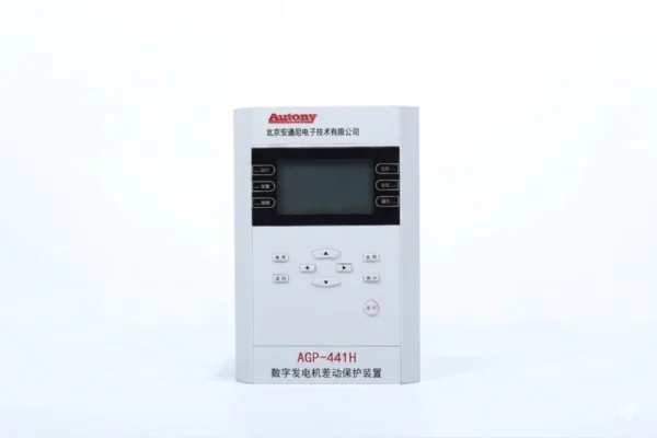
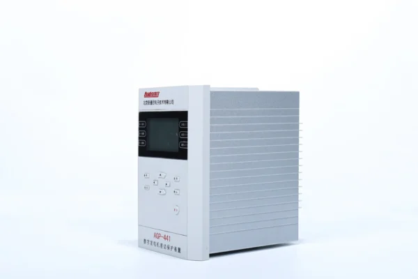
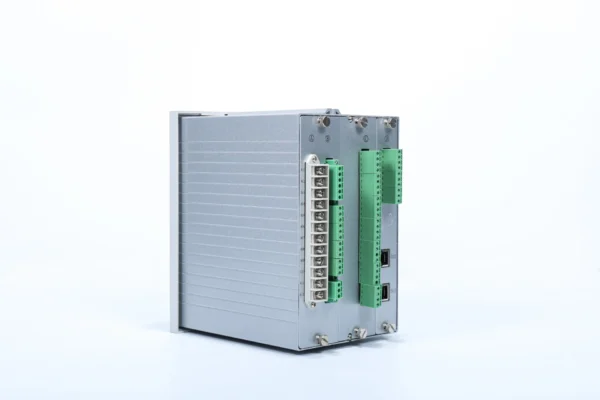
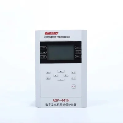
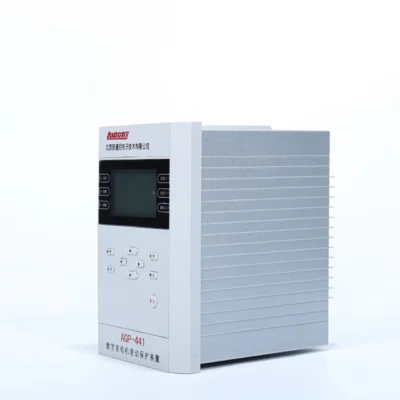
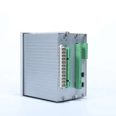
Generator Differential Protection Relay 87G
The AGP-441H is a digital generator differential protection relay designed for generators up to 100 MW. It provides phase-separated 87G and 87GH differential protection, fast internal fault tripping, CT open-circuit detection and flexible communication interfaces for power plant protection and control systems.
Product Functions (ANSI):87GH/87G
Communication Mode:Optional: RS-485, CAN bus, Ethernet, IEC 60870-5-103 (IEC-103)
Send your requirements, we will quote for you within 12 hours
Description
Overview
The AGP-441H is a digital generator differential protection relay designed for generators up to 100 MW. It provides phase-separated 87G and 87GH differential protection, fast internal fault tripping, CT open-circuit detection and flexible communication interfaces for power plant protection and control systems.
Key Features
- Generator Capacity: ≤100 MW
- Protection: 87G / 87GH
- Protection Type: Phase-separated differential protection
- High-Speed Trip: ≤25 ms for differential high-set protection
- CT Protection: CT open-circuit detection and blocking
- Communication: RS-485 / CAN / Ethernet / IEC 60870-5-103
- Installation: Panel integrated or distributed installation
Function Configuration
Protection Configuration
| Protection Function | Description |
|---|---|
| Differential fast trip | — |
| Percentage differential protection | With second-harmonic blocking |
| Differential current over-limit alarm | — |
| Non-electrical protection | — |
Monitoring and Control Functions
| Category | Parameters |
|---|---|
| Protection current | ia1, ib1, ic1, ia2, ib2, ic2 |
| Frequency | F |
| Item | Specification |
|---|---|
| Digital inputs | 21 channels (AC/DC220V, DC100V, or DC48V; to be specified when ordering) |
| Protection outputs | 11 channels |
| Signal outputs | 2 channels |
| Device loss-of-power output | 1 channel |
Communication Functions
| Item | Specification |
|---|---|
| Ethernet ports | 2 ports |
| RS485 ports | 2 ports (the second is shared with time sync port; selectable via setting) |
| Protocols | Internal Ethernet 103, SAC Ethernet 103, MODBUS RTU |
Time Synchronization Function
| Time Sync Method | Support |
|---|---|
| Communication message time sync | ✓ |
| SNTP time sync | ✓ |
| IRIG-B time sync | ✓ |
Printing Function
| Item | Description |
|---|---|
| Printer support | Supports dot matrix printer with serial communication |
| Printable content | Settings, event records, waveform records, etc. |
Protection Information Functions
| Function | Support |
|---|---|
| Remote view of device description | ✓ |
| Remote view of device parameter settings | ✓ |
| Remote view and modification of protection settings and zone numbers | ✓ |
| Remote view, remote control, and local enable/disable of soft pressure plates | ✓ |
| Remote view of device protection digital input status | ✓ |
| Remote view of device operating status (protection element status, self-check alarms, etc.) | ✓ |
| Remote signal reset |
Ordering Instructions
-
Product model, name, and order quantity;
-
Rated AC current of current transformer: 1A/5A;
-
Device operating power supply voltage level: AC/DC220V, DC110V, DC48V;
-
Digital input module voltage level: AC/DC220V, DC110V, DC48V;
-
Whether the DC input/output function is required (optional);
-
Delivery address and schedule;
-
Important notes / special requirements.
What Does the 87G Generator Differential Relay Protect?
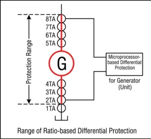
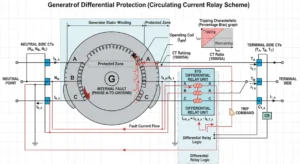
The 87G differential relay protects the generator stator zone defined by the terminal-side and neutral-side CTs.
| Protection Zone | Main Protection |
|---|---|
| Generator stator winding | 87G |
| Generator internal phase faults | 87G |
| Generator terminal connections | 87G, depending on CT arrangement |
| Differential high-set faults | 87GH |
87G and 87GH Generator Differential Protection
Generator differential protection consists of two coordinated functional elements: 87G (sensitive differential element) and 87GH (high-speed high-set element), which together form the complete primary protection for the generator stator.
Function Comparison
| Function | ANSI | Purpose |
|---|---|---|
| Generator Differential Protection | 87G | Sensitive protection for internal faults |
| Generator Differential High-Set | 87GH | Ultra-high-speed unrestrained tripping for severe internal faults |
How They Work Together
-
87G – Uses percentage restraint to provide high-sensitivity detection of internal faults while remaining stable during CT saturation caused by external faults
-
87GH – Set at 3–8 × rated current, unrestrained, provides ultra-high-speed instantaneous operation for severe faults
Minor internal faults: only 87G operates. Severe faults: both 87G and 87GH operate simultaneously. External faults: both remain stable.
Phase-Separated Differential Protection
The relay employs phase-separated differential protection—differential current and fault discrimination are calculated independently for each of the three phases (A, B, and C).
-
Fault phase identification – accurately locates the faulted phase, speeding up analysis and restoration
-
High selectivity – prevents a single-phase fault from tripping all three phases
Applications of Generator Differential Protection Relay 87G
Generator differential protection relay 87G is the primary protection for internal stator faults, widely applied across various power generation scenarios. Actual configuration should be selected based on generator capacity, voltage level, CT arrangement, and protection requirements.
Hydropower Generators
| Item | Description |
|---|---|
| Capacity Range | 1MW ~ 800MW+ |
| Voltage Level | 400V ~ 13.8kV and above |
| Configuration Notes | Large units use split-phase differential protection for turn-to-turn faults; >100MW units recommend dual redundant configuration; coordinate with 64S for 100% stator ground protection |
Thermal Power Generators
| Item | Description |
|---|---|
| Capacity Range | 100MW ~ 1000MW+ |
| Voltage Level | 11kV ~ 24kV |
| Configuration Notes | Large units use dual redundant configuration; special attention to CT saturation; coordinate with 87GT generator-transformer protection |
Gas Turbine Generators
| Item | Description |
|---|---|
| Capacity Range | 10MW ~ 400MW |
| Voltage Level | 6.6kV ~ 13.8kV |
| Configuration Notes | Frequent start/stop requires attention to second-harmonic restraint; validate stability under load fluctuations during peaking; often used with 87GT |
Industrial Generators
| Item | Description |
|---|---|
| Capacity Range | 1MW ~ 100MW |
| Voltage Level | 400V ~ 11kV |
| Configuration Notes | Island mode requires special settings; high immunity to interference required; low-impedance differential preferred where space is limited |
Diesel Generator Sets
| Unit Capacity | 87G Configuration Recommendation |
|---|---|
| <500kW | Generally not configured (overcurrent 50/51 is primary) |
| 500kW ~ 1MW | Optional based on project requirements |
| >1MW | Recommended |
| Grid-connected | Mandatory (regardless of capacity) |
Note: Not all diesel generators require 87G protection—small standby units are typically protected by overcurrent protection alone.
Configuration Selection Summary
| Application | Typical Capacity | 87G Recommendation | Key Coordinated Protections |
|---|---|---|---|
| Hydro Units | 1~800MW+ | Standard (dual redundant for large units) | 64S, 64R, 32, 81 |
| Thermal Units | 100~1000MW+ | Standard (dual redundant) | 87GT, 50/51, 40, 32 |
| Gas Turbines | 10~400MW | Standard | 87GT, 50/51, 81, 32 |
| Industrial Generators | 1~100MW | Based on capacity | 50/51, 46, 32, 40 |
| Diesel Units | >1MW recommended; mandatory for grid-connected | Based on capacity and grid status | 50/51, 32, 25 |
Important Reminders
-
No universal solution—each generator must be designed individually
-
Small units may not require 87G—overcurrent protection may be sufficient
-
Grid-connected generators typically require differential protection
-
87G must coordinate with backup protections (50/51, 32, etc.)
Final configuration should be designed by qualified protection engineers based on specific project parameters.
87G Generator Differential Protection – FAQ
1. What is a generator differential protection relay 87G?
The 87G generator differential protection relay is the primary high-speed protection device for detecting internal faults within a generator’s stator windings. It continuously compares currents measured by CTs on the generator terminal side and neutral side. Under normal conditions or external faults, the currents are equal and the differential current is near zero. When an internal stator fault occurs (such as a phase-to-phase short circuit, turn-to-turn fault, or insulation failure), the currents become unequal, generating a differential current that triggers an instantaneous trip command to isolate the generator from the system.
2. What does an 87G generator differential relay protect?
The 87G relay protects the generator stator zone defined by the terminal-side and neutral-side CTs, including:
| Protected Item | Description |
|---|---|
| Stator windings | Primary protection zone |
| Phase-to-phase faults | Short circuits between phases |
| Three-phase faults | Symmetrical short circuits |
| Phase-to-ground faults | Within the CT-defined zone |
| Turn-to-turn faults | Sensitivity depends on fault location and settings |
The 87G relay does not protect: external system faults, transformer faults, rotor faults, loss of excitation, reverse power, or overload conditions—these require separate protection functions.
3. What is the difference between 87G and 87GH protection?
| Feature | 87G | 87GH |
|---|---|---|
| Function | Sensitive differential protection | High-set differential protection |
| Pickup Setting | 0.1–0.3 × rated current | 3–8 × rated current |
| Restraint | Dual-slope percentage restraint | No restraint |
| Operating Speed | Fast (with restraint delay) | Ultra-high-speed (instantaneous) |
| Application | All internal faults | Severe internal faults only |
How they work together: For minor internal faults, only 87G operates. For severe faults (e.g., high-magnitude short circuits), both 87G and 87GH operate simultaneously. During external faults with CT saturation, 87G remains stable due to its restraint characteristic, while 87GH remains stable due to its high pickup setting.
4. What CTs are required for generator differential protection?
Generator differential protection requires two sets of three-phase CTs:
| CT Location | Purpose |
|---|---|
| Generator terminal side (line side) | Measures current leaving the generator |
| Generator neutral side | Measures current entering the generator |
Key CT requirements:
-
CT ratio must be properly matched between both sides
-
CT polarity must be correctly verified during commissioning
-
CT accuracy class must be suitable for protection applications
-
CT saturation performance must be considered for external fault stability
-
Modern relays can compensate for ratio mismatches using internal ratio matching
5. How does the 87G relay handle CT open-circuit conditions?
Modern 87G relays include dedicated CT open-circuit detection to prevent relay maloperation and protect personnel.
When a CT open circuit occurs:
-
The relay detects the abnormal condition by monitoring current imbalance and voltage presence
-
It issues an alarm to alert operators, rather than a trip command
-
The affected phase is typically blocked from differential protection operation to prevent false tripping
-
The remaining healthy phases continue to provide protection
Typical detection logic:
-
One phase current is near zero while voltage is present
-
Other phase currents are normal
-
The relay determines this is a CT circuit failure rather than an internal generator fault
6. What generators can the 87G relay protect?
The 87G relay is suitable for a wide range of generator types and capacities:
| Generator Type | Capacity Range | Voltage Level |
|---|---|---|
| Hydropower generators | 1MW – 800MW+ | 400V – 13.8kV+ |
| Thermal power generators | 100MW – 1000MW+ | 11kV – 24kV |
| Gas turbine generators | 10MW – 400MW | 6.6kV – 13.8kV |
| Industrial generators | 1MW – 100MW | 400V – 11kV |
| Diesel generator sets | >1MW (recommended) | 400V – 6.6kV |
Selection guidance:
-
Generators >1MW: Recommended to configure 87G protection
-
Grid-connected generators: Mandatory regardless of capacity
-
Generators <500kW: Typically protected by overcurrent (50/51) without 87G
7. What communication protocols does the generator differential protection relay support?
Modern generator differential protection relays support multiple communication protocols for seamless SCADA and plant control system integration:
| Protocol | Typical Application |
|---|---|
| IEC 61850 | Modern digital substations; supports GOOSE messaging |
| IEC 60870-5-103 | Serial communication for protection relays |
| IEC 60870-5-104 | WAN communication between control centers and substations |
| Modbus RTU | Serial (RS-485) for local SCADA and PLC integration |
| Modbus TCP | Ethernet-based for faster network communication |
| DNP3 | North American utility standard |
Supported data exchange:
-
Analog measurements (voltage, current, power, frequency)
-
Status indications (breaker position, relay health, alarms)
-
Protection events and trip records
-
Control commands (remote breaker open/close, reset)
Other Generator Protection Equipment
64R Rotor Earth Fault Protection Relay | Voltage Injection
400V Low Voltage Hydroelectric Generator Protection Relay
441H generator backup protection relay
87G/50/51 Generator Protective Relay
2 reviews for Generator Differential Protection Relay 87G
Related products
High Quality
Stable performance, reliable design, ensuring safe operation for power system protection and grid stability.
Fast Delivery
Timely delivery to support your urgent orders and project schedules efficiently and professionally at any time.
Best Warranty
Professional Warranty: Reliable after-sales support for stable relay protection and long-term customer satisfaction.
xiao zhang –
Generator differential protection relay (ANSI 87G) is the main protection for generators. It uses percentage restraint algorithm with strong anti-CT-saturation performance and CT break blocking, fast tripping for stator internal faults, available with multi-communication for global generator projects.
Jack –
Rugged enclosure design holds up well in industrial substations.