

-
Leon Zhang sales consultant
-
Email: zxl635973785@gmail.com
-
Phone/WhatsApp: +86 13655813266
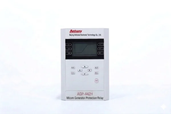
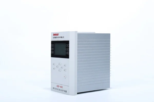
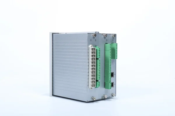
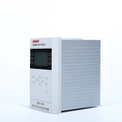
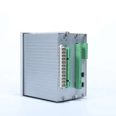
87G/50/51 Generator Protective Relay
Overview of Gengenerator Protective Relay
Gengenerator Protective Relay belongs to generator protective relays, which is suitable for differential and backup protection of small generators, as well as protection for hydro-generators up to 2 MW and turbine generators up to 10 MW.
Generator Protective Relay Numbers(ANSI):
87/87G/50/51/49/46/50N/51N/40/32/81O/81U/59/27/59N/60/63/27
Communication Mode:Optional: RS-485, CAN bus, Ethernet, IEC 60870-5-103 ,IEC 61850
Send your requirements, we will quote for you within 12 hours
Description
Overview of Generator Protective Relay
- Generator Protective Relay belongs to generator protective relays, which is suitable for differential and backup protection of small generators, as well as protection for hydro-generators up to 2 MW and turbine generators up to 10 MW.
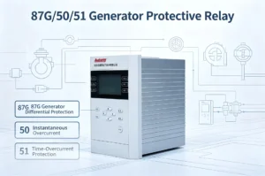
Features and Specifications
- Differential Instantaneous Trip (Trip)
- Percentage Differential Protection (Trip)
- Excessive Differential Current (Alarm)
- Three-stage Overcurrent Protection (Trip)
- Inverse-time Overcurrent (Trip; Normal / Severe / Extreme mode optional)
- Overload Protection (Alarm / Trip optional)
- Two-stage Negative Sequence Overcurrent Protection (Stage I: Trip; Stage II: Alarm / Trip optional)
- Inverse-time Negative Sequence Overcurrent (Trip)
- Three-stage Zero-sequence Overcurrent (Stage I/II: Trip; Stage III: Alarm / Trip optional)
- Loss of Excitation Protection (Trip)
- Reverse Power Protection (Trip)
- Overfrequency Protection (Trip)
- Underfrequency Protection (Trip)
- Overvoltage Protection (Trip)
- Undervoltage Protection (Alarm / Trip optional, with current blocking)
- Zero-sequence Overvoltage Protection (Alarm / Trip optional)
- PT Circuit Disconnection (Alarm)
- CT Circuit Disconnection (Alarm)
- Control Circuit Disconnection (Alarm)
- Non-electrical Quantity Protection (Alarm / Trip optional)
- PT Voltage Loss (Alarm)
- System Power Loss (Alarm / Trip optional)
Generator Protection Relay Numbers(ANSI):
- 87/87G/50/51/49/46/50N/51N/40/32/81O/81U/59/27/59N/60/63/27
50/51 Overcurrent Protection for Generators
What Is a 50/51 Relay?
A 50/51 relay combines instantaneous overcurrent protection (ANSI 50) and time overcurrent protection (ANSI 51) to protect generators against excessive current caused by short circuits, overloads and external system faults.
What is the difference between 50 and 51 protection?
| Protection Function | ANSI Code | Operating Characteristic | Main Purpose |
|---|---|---|---|
| Instantaneous Overcurrent | 50 | No intentional time delay | High-current short-circuit protection |
| Time Overcurrent | 51 | Inverse or definite time delay | Overload and backup fault protection |
| 50/51 | 50 + 51 | Instantaneous + time-delayed | Comprehensive overcurrent protection |
Generator 50/51 Protection Working Principle
How Does 50/51 Generator Protection Work?
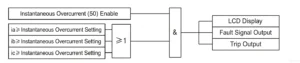
50/51 Relay Settings
The 50/51 generator protection settings depend on generator rated current, CT ratio, generator short-circuit withstand capability, overload capability, neutral grounding method, downstream protection coordination requirements, breaker clearing time and system fault level.
50/51 vs 87G Generator Protection
| Feature | 50/51 | 87G |
|---|---|---|
| Protection Type | Overcurrent | Differential |
| ANSI Function | 50/51 | 87G |
| Main Protection Area | Backup/external faults | Internal generator faults |
| Operating Principle | Current magnitude + time | Current differential |
| Typical Application | Backup protection | Main generator protection |
| Speed | 50 is fast; 51 is time delayed | High-speed |
| CT Requirement | Current measurement CT | Differential CT arrangement |
87G is generally used as the main protection for internal generator faults, while 50/51 overcurrent protection can provide backup protection for external faults and abnormal overcurrent conditions.
Generator 50/51 Protection Working PrincipleMeasurement and Control Functions
- Busbar voltage: Ua, Ub, Uc, Uab, Ubc, Uca;
- Measured current: Ia, Ic;
- Power: P, Q, COSφ;
- Frequency: f;
- Electric energy: EP+, EP-, EQ+, EQ-;
- Supports 21-channel active binary inputs (AC/DC 220V, DC 100V or DC 48V; voltage level shall be specified when ordering);
- Equipped with 11 protection output channels, 2 signal output channels, 1 closing position signal output channel, and 1 device power-loss output channel.
Communication Functions
| Item | Description |
|---|---|
| Communication Interfaces | 2 × Ethernet ports
2 × RS485 ports (2nd port shared with time sync, selectable via configuration) |
| Communication Protocols | IEC-103, IEC-61850, Modbus |
| Time Synchronization | Communication message, SNTP, IRIG-B |
| Printing Function | Compatible with serial dot-matrix printers; prints settings, event logs and fault waveforms |
Generator Protective Relay Settings
| No. | Setting Name | Setting Range | Unit | Default Value | Remarks |
|---|---|---|---|---|---|
| 1 | Differential Starting Current | 0.1–100 | A | 1 | |
| 2 | Differential Instantaneous Setting | 0.1–100 | A | 5 | |
| 3 | Inflection Point Setting | 0.1–100 | A | 1 | |
| 4 | Ratio Restraint Coefficient | 0.1–0.9 | — | 0.5 | |
| 5 | Generator Rated Current | 0.1–100 | A | 5 | |
| 6 | Overcurrent Stage I Setting | 0.1–100 | A | 8 | |
| 7 | Overcurrent Stage II Setting | 0.1–100 | A | 7 | |
| 8 | Overcurrent Stage II Time Delay | 0–100 | S | 0.5 | |
| 9 | Overcurrent Stage III Setting | 0.1–100 | A | 5 | |
| 10 | Overcurrent Stage III Time Delay | 0–100 | S | 1 | |
| 11 | Undervoltage Blocking Current Setting | 1–400 | V | 70 | |
| 12 | Negative Voltage Blocking Current Setting | 1–400 | V | 10 | |
| 13 | Inverse-time Overcurrent Setting | 0.1–100 | A | 5 | |
| 14 | Inverse-time Overcurrent Time Delay | 0–100 | S | 1 | |
| 15 | Inverse-time Overcurrent Type | 0–3 | — | 1 | 1=Normal, 2=Severe, 3=Extreme |
| 16 | Overload Setting | 0.1–100 | A | 5 | |
| 17 | Overload Time Delay | 0–100 | S | 2 | |
| 18 | Overload Type | 0–2 | — | 1 | 0=Exit, 1=Trip, 2=Alarm |
| 19 | Negative Sequence Overcurrent Stage I Setting | 0.1–100 | A | 2 | |
| 20 | Negative Sequence Overcurrent Stage I Time Delay | 0–100 | S | 1 | |
| 21 | Negative Sequence Overcurrent Stage II Setting | 0.1–100 | A | 1 | |
| 22 | Negative Sequence Overcurrent Stage II Time Delay | 0–100 | S | 2 | |
| 23 | Negative Sequence Overcurrent Stage II Type | 0–2 | — | 1 | 0=Exit, 1=Trip, 2=Alarm |
| 24 | Negative Sequence Inverse-time Overcurrent Setting | 0.1–100 | A | 5 | |
| 25 | Negative Sequence Inverse-time Overcurrent Time Delay | 0–100 | S | 1 | |
| 26 | Negative Sequence Inverse-time Overcurrent Type | 0–3 | — | 1 | 1=Normal, 2=Severe, 3=Extreme |
| 27 | Zero-sequence Overcurrent Stage I Setting | 0.1–100 | A | 2 | |
| 28 | Zero-sequence Overcurrent Stage I Time Delay | 0–100 | S | 0.2 | |
| 29 | Zero-sequence Overcurrent Stage II Setting | 0.1–100 | A | 2 | |
| 30 | Zero-sequence Overcurrent Stage II Time Delay | 0–100 | S | 1 | |
| 31 | Zero-sequence Overcurrent Stage III Setting | 0.1–100 | A | 2 | |
| 32 | Zero-sequence Overcurrent Stage III Time Delay | 0–100 | S | 2 | |
| 33 | Zero-sequence Overcurrent Stage III Type | 0–2 | — | 1 | 0=Exit, 1=Trip, 2=Alarm |
| 34 | Zero-voltage Blocking Zero-sequence Setting | 1–400 | V | 5 | |
| 35 | Loss of Excitation Impedance Setting A | 0–100 | — | 1 | |
| 36 | Loss of Excitation Impedance Setting B | 0.2–200 | — | 20 | |
| 37 | Loss of Excitation Protection Time Delay | 0–100 | S | 1 | |
| 38 | Undervoltage Blocking Loss of Excitation Setting | 1–400 | V | 10 | |
| 39 | Reverse Power Protection Setting | 0–600 | W | 50 | |
| 40 | Reverse Power Time Delay | 0–100 | S | 1 | |
| 41 | Overvoltage Setting | 1–600 | V | 120 | |
| 42 | Overvoltage Time Delay | 0–100 | S | 0.5 | |
| 43 | Undervoltage Setting | 1–400 | V | 80 | |
| 44 | Undervoltage Time Delay | 0–100 | S | 1 | |
| 45 | Zero-sequence Overvoltage Setting | 1–400 | V | 30 | |
| 46 | Zero-sequence Overvoltage Time Delay | 0–100 | S | 0.5 | |
| 47 | Zero-sequence Overvoltage Type | 0–2 | — | 1 | 0=Exit, 1=Trip, 2=Alarm |
| 48 | Overfrequency Protection Setting | 35–65 | Hz | 51 | |
| 49 | Overfrequency Protection Time Delay | 0–100 | S | 0.5 | |
| 50 | Underfrequency Protection Setting | 35–60 | Hz | 49 | |
| 51 | Underfrequency Protection Time Delay | 0–100 | S | 0.5 | |
| 52 | Undervoltage Blocking Frequency Setting | 1–400 | V | 20 | |
| 53 | Slip Blocking Frequency Setting | 1–30 | Hz/S | 3 | |
| 54 | PT Disconnection Time Delay | 0–100 | S | 5 | |
| 55 | PT Voltage Loss Time Delay | 0–100 | S | 5 | |
| 56 | Control Circuit Disconnection Time Delay | 0–100 | S | 10 | |
| 57 | System Power Loss Type | 0–2 | — | 1 | 0=Exit, 1=Trip, 2=Alarm |
| 58 | Thermal/Hydraulic Accident Type | 0–2 | — | 1 | |
| 59 | Thermal/Hydraulic Accident Time Delay | 0–100 | S | 0.1 | |
| 60 | Excitation Fault Type | 0–2 | — | 1 | |
| 61 | Excitation Fault Time Delay | 0–100 | S | 0.1 | |
| 62 | Electrical Accident Type | 0–2 | — | 1 | |
| 63 | Electrical Accident Time Delay | 0–100 | S | 0.1 |
Note: Refer to the manual for generator protection relay setting calculation instructions.
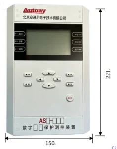
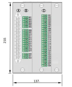
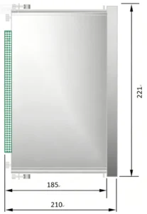
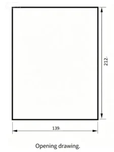
Outline and Installation Dimensions of Generator Protective Relay
FAQ
Q:which relay is used for generator protection relay?
Generator out of step protection relays, reverse power relay for generator protection, three-stage generator current protection, generator loss-of-field protection, generator rotor protection relay,generator differential protection, etc.
Q:which relay is used for Gengenerator Protective Relay?
The Gengenerator Protective Relay price is generally around 6,000 RMB, with higher-specification models costing more.
Q:What is a generator protective relay?
A dedicated numerical IED for generator units, monitoring electrical faults and abnormal operating conditions, sending trip or alarm signals to protect the generator stator, rotor and prime mover.
Q:What core ANSI protection functions are included?
87G Stator Differential, 50/51 Overcurrent, 59 Overvoltage, 27 Undervoltage, 46 Negative Sequence Current, 32 Reverse Power, 64R Rotor Earth Fault, 81 Frequency Protection, Out-of-Step Protection.
Q:When will out-of-step protection operate?
The generator loses synchronization with the power grid; it separates the unit from the grid to prevent system oscillation and unit mechanical damage.
Q:Linkage with synchronization panel
The relay blocks the closing circuit if the unit has faults during paralleling, forbids out-of-phase synchronization.
Q:What is a 50/51 relay?
A 50/51 relay integrates ANSI 50 instantaneous overcurrent protection and ANSI 51 time-overcurrent protection within one unit. It delivers combined instantaneous and time-delayed overcurrent protection for generators, transformers, motors and other power equipment.
Q:What does ANSI 50 mean?
ANSI 50 stands for Instantaneous Overcurrent Protection. It operates with no intentional time delay once the measured current exceeds the pickup threshold, mainly used to clear severe short-circuit faults quickly.
Q:What does ANSI 51 mean?
ANSI 51 refers to Time-Overcurrent Protection. It trips after a preset delay (definite or inverse time characteristic) when overcurrent persists, designed for overloads and mild faults.
Q:What is the difference between 50 and 51 relay?
ANSI 50 is instantaneous overcurrent protection with zero intentional delay for heavy short circuits.ANSI 51 is time-overcurrent protection with adjustable delay to cover overloads and coordinate with other protective devices.50 responds to high-magnitude fault current; 51 handles sustained moderate overcurrent.
Q:What does a 50/51 relay protect against?
It protects equipment against phase short circuits, external system faults, sustained overloads and abnormal overcurrent conditions. For generators, it serves as backup protection when main protection fails to operate.
Q:How do you set a 50/51 generator relay?
Settings are determined by generator rated current, CT ratio, generator short-circuit withstand capability, overload capacity, neutral grounding scheme, downstream protection coordination, breaker clearing time and system fault level. No universal fixed values apply.
Q:What is the difference between 50/51 and 87G?
87G (Generator Differential Protection) is the main protection for internal generator winding faults.50/51 overcurrent protection acts as backup protection. It cannot sensitively detect internal winding faults, but covers external short circuits and generator overloads.
Other Generator Protection Equipment
400V Low Voltage Hydroelectric Generator Protection Relay
2 reviews for 87G/50/51 Generator Protective Relay
Related products
High Quality
Stable performance, reliable design, ensuring safe operation for power system protection and grid stability.
Fast Delivery
Timely delivery to support your urgent orders and project schedules efficiently and professionally at any time.
Best Warranty
Professional Warranty: Reliable after-sales support for stable relay protection and long-term customer satisfaction.
xiao zhang –
Provides full-range motor protection including differential and backup protection, rapidly isolating faults to ensure motor safe and stable operation.
Jack –
Works seamlessly with SCADA systems — no communication dropouts.