-
Leon Zhang sales consultant
-
Email: zxl635973785@gmail.com
-
Phone/WhatsApp: +86 13655813266

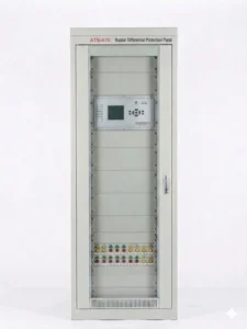
87B Busbar Differential Protection Panel Introduction
Overview of Busbar Differential Protection Panel
The busbar differential protection panel serves as the core main protection cabinet for busbar fault protection in substations and power plants. Based on Kirchhoff’s Current Law, it collects real-time current data of all connected components including power lines, transformers and bus couplers on the busbar.
The busbar differential protection panel complies with international IEC 61850 standards.
In-house Factory & Technical Team, OEM ODM Custom Electrical Equipment
Send your requirements, we will quote for you within 12 hours
Description
Overview of Busbar Differential Protection Panel
- The busbar differential protection panel serves as the core main protection cabinet for busbar fault protection in substations and power plants. Based on Kirchhoff’s Current Law, it collects real-time current data of all connected components including power lines, transformers and bus couplers on the busbar.
- By adopting differential protection principle, it rapidly identifies internal short-circuit faults of the busbar, trips off all circuit breakers of the faulty busbar instantly to isolate faults and prevent accident expansion, so as to ensure stable power grid operation.
- It is applicable to various voltage levels from 35kV to 500kV, covering single busbar, sectionalized single busbar, double busbar and 3/2 breaker connection modes. It features fast response speed, high selectivity and strong anti-CT saturation capability.
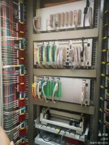
Composition
The standard cabinet is designed with unified dimensions, equipped with front operating components and rear wiring layout. Main internal components are as follows:
- Busbar Differential Protection Device: Core control unit realizing ratio restraint differential protection, fault section selection and trip output, compatible with mainstream communication protocols.
- Bus Coupler Protection & Control Unit: Responsible for bus coupler charging protection, overcurrent protection, breaker failure protection and switch position signal collection.
- Compound Voltage Lockout Device: Realizes undervoltage, negative sequence and zero-sequence voltage lockout to avoid mal-operation.
- Communication Manager & Network Switch: Implements protocol conversion, data upload and unified satellite time synchronization.
- DC Power Supply Module: Provides stable working power for all internal devices with redundant design.
- CT & PT Secondary Circuit: Accesses current and voltage signals for protection logic judgment.
- Operating Buttons, Pressure Plates & Touch Screen: For function switching, fault alarm display and local onsite operation.
Main Functions
Core Differential Protection Function
- Adopts split-phase total difference and sectional difference logic, effectively avoiding unbalanced current under external faults. It can rapidly respond to various busbar short-circuit faults and complete selective tripping.
Auxiliary Protection Functions
- Supports bus coupler charging protection, breaker failure protection, dead zone protection, CT/PT disconnection alarm and compound voltage lockout protection.
Measurement, Control & Communication Functions
- Collects real-time electrical parameters and switch status, supports fault wave recording, event record query, remote parameter setting and self-diagnosis. It fully supports IEC 61850, Modbus TCP/IP and other mainstream power communication protocols.
Installation and Commissioning
Installation Requirements
- Install in dry, dust-proof and anti-electromagnetic interference indoor environment. Reserve sufficient operation and maintenance space, implement standard cabinet grounding, and adopt shielded cables for secondary signal wiring with standardized wiring specifications.
Commissioning Steps
- Check appearance, wiring and insulation performance before power-on.
- Conduct power-on self-inspection to confirm normal operation of all devices.
- Calibrate current and voltage sampling signals to ensure correct polarity and accurate data.
- Test differential protection action characteristics and set reasonable operating parameters.
- Complete whole-group trip transmission test to verify protection logic accuracy.
- Finish communication debugging and time synchronization calibration.
- Put into trial operation with load after confirming all indexes meet standards.
Selection Method
- Select matching protection configuration according to actual voltage level and busbar connection mode.
- Confirm the number of connected branch circuits to choose standard or extended-type devices.
- Prioritize products with fast tripping speed and strong anti-CT saturation performance.
- Select corresponding communication versions for conventional substations and smart substations respectively.
- Follow power industry design standards to adopt dual redundant configuration for high-voltage power grids above 220kV.
- Determine internal equipment configuration and reserved functions based on actual project technical requirements.
Supplementary Description
- Busbar differential protection panels belong to non-standard customized power protection cabinets. There is no unified fixed configuration standard for all projects. The internal equipped devices, functional allocation and overall design shall all be implemented in accordance with specific project design drawings and technical specifications.
Methods for Selecting Busbar Differential Protection Panel
| Selection Criteria | Description |
|---|---|
| Select by voltage grade | Match protection type by system voltage. Low & medium voltage: ordinary busbar differential protection; Above 220kV high voltage: dual configuration differential protection |
| Select by busbar connection mode | Adapt to single busbar, sectionalized busbar, double busbar and 3/2 breaker wiring |
| Confirm branch circuit quantity | Select standard or extended panel based on incoming lines, outgoing lines and transformer branches |
| Check core technical performance | Prioritize products with fast tripping, strong anti-CT saturation and reliable fault discrimination |
| Distinguish substation type | Conventional substation: traditional protocol; Smart substation: full IEC 61850 optical fiber communication |
| Follow power design standards | Key high-voltage power stations adopt dual redundant protection for higher operational safety |
| Confirm on-site operating demands | Select configurations of local touch screen, remote control and fault recording as required |
| Determine customized configuration | Equip communication management unit, switch, power supply and other internal devices per project needs |
| Verify after-sales and compatibility | Ensure compatibility with existing automation system and easy maintenance |
FAQ
Q:What types of substations generally need to be equipped with busbar differential protection panels?
A:Busbar differential protection panels are required for 110kV and above substations, hub stations and those with double busbar wiring. With numerous incoming and outgoing lines, they need fast fault isolation to ensure grid stable operation.
2 reviews for 87B Busbar Differential Protection Panel Introduction
Related products


High Quality
Stable performance, reliable design, ensuring safe operation for power system protection and grid stability.
Fast Delivery
Timely delivery to support your urgent orders and project schedules efficiently and professionally at any time.
Best Warranty
Professional Warranty: Reliable after-sales support for stable relay protection and long-term customer satisfaction.
xiao zhang –
Busbar Differential Protection Panel provides fast and reliable busbar fault detection and tripping, effectively protecting power system safety.
Jack –
The equipment runs steadily and is highly reliable for field use.