-
Leon Zhang sales consultant
-
Email: zxl635973785@gmail.com
-
Phone/WhatsApp: +86 13655813266


Automatic Bus Transfer Switch 83B
Overview of Automatic Bus Transfer Switch (ABTS)
The ASZ-441H sectionalized standby power automatic transfer switch, as a typical Automatic Bus Transfer Switch and core unit of the automatic bus transfer system, can automatically disconnect the main power supply upon power failure or circuit interruption, close the sectionalized circuit breaker, and complete fast automatic transfer to the standby power supply.
ANSI:25/51V/50/51/60
Communication Mode:Optional: RS-485, CAN bus, IEC 61850 , IEC 60870-5-103
In-house Factory & Technical Team, OEM ODM Custom Electrical Equipment
Send your requirements, we will quote for you within 12 hours
Description
Overview of Automatic Bus Transfer Switch (ABTS)
- The ASZ-441H sectionalized standby power automatic transfer switch, as a typical Automatic Bus Transfer Switch and core unit of the automatic bus transfer system, can automatically disconnect the main power supply upon power failure or circuit interruption, close the sectionalized circuit breaker, and complete fast automatic transfer to the standby power supply.
Automatic Bus Transfer Features
- Automatic Bus Transfer Function — ANSI 25
- Compound Voltage Initiated Overcurrent Protection — ANSI 51V
- Charging Protection — ANSI 50/51
- Overload Protection — ANSI 51
- PT/VT Broken Circuit Supervision — ANSI 60
Communication Mode
- Optional: RS-485, CAN bus, Ethernet,IEC 61850 , IEC 60870-5-103
Main Functional Specifications
- Protection response time (including the response time of the output relay): Average error in response time: not more than 35 ms;
- Precision operating range: Minimum precision current: 0.08 In, Maximum precision current: 20 In
- Current setting error: When the current exceeds 1.00 A, the error shall not exceed ±2.5%; Voltage setting error: shall not exceed ±3%
- Measurement accuracy: Current (I)/Voltage (U): Class 0.2; Power (P)/Reactive power (Q): Class 0.5
- Remote signal resolution: no more than 2 ms
Event Logging, Fault Recording
- The recorded events include protective action events and device malfunctions;
- Record the type of protection trip, the time of the trip, and the operating parameters at the time of the trip;
- The fault recording data includes: the time of the protection operation, the type of protection operation, and the rms values before and after the recording was initiated;
- Data length of the fault recording: 2 cycles before the fault and 4 cycles after the fault;
- The SOE can retain 48 sets of data after a power loss, and the fault report can retain 16 sets of data after a power loss.
ATS Controller with ANSI 27/59 Protection – Setting List
| No. | Display Name | Range | Step | Remark |
|---|---|---|---|---|
| 1 | Stage 1 Protection Configuration | — | — | |
| 1.1 | Stage 1 Protection | 1/0 | — | Stage 1 Protection: Enable(1) / Disable(0) |
| 1.2 | Stage 1 Compound Voltage Locking | 1/0 | — | Stage 1 Compound Voltage Locking: Enable(1) / Disable(0) |
| 1.3 | Stage 1 Time Delay | 0~120.00s | 0.01s | |
| 1.4 | Stage 1 Setting Value | 0.40~99.99A
0.10~20.00A |
0.01A | In=5A: 0.40~99.99A
In=1A: 0.10~20.00A |
| 2 | Stage 2 Protection Configuration | — | — | |
| 2.1 | Stage 2 Protection | 1/0 | — | Stage 2 Protection: Enable(1) / Disable(0) |
| 2.2 | Stage 2 Compound Voltage Locking | 1/0 | — | Stage 2 Compound Voltage Locking: Enable(1) / Disable(0) |
| 2.3 | Stage 2 Time Delay | 0~120.00s | 0.01s | |
| 2.4 | Stage 2 Setting Value | 0.40~99.99A
0.10~20.00A |
0.01A | In=5A: 0.40~99.99A
In=1A: 0.10~20.00A |
| 3 | Stage 3 Protection Configuration | — | — | |
| 3.1 | Stage 3 Protection | 1/0 | — | Stage 3 Protection: Enable(1) / Disable(0) |
| 3.2 | Stage 3 Compound Voltage Locking | 1/0 | — | Stage 3 Compound Voltage Locking: Enable(1) / Disable(0) |
| 3.3 | Stage 3 Time Delay | 0~120.00s | 0.01s | |
| 3.4 | Stage 3 Setting Value | 0.40~99.99A
0.10~20.00A |
0.01A | In=5A: 0.40~99.99A
In=1A: 0.10~20.00A |
| 4 | Bus Charging Protection | — | — | |
| 4.1 | Bus Charging Protection | 1/0 | — | Bus Charging Protection: Enable(1) / Disable(0) |
| 4.2 | Charging Time Delay | 0~120.00s | 0.01s | |
| 4.3 | Charging Setting Value | 0.40~99.99A
0.10~20.00A |
0.01A | In=5A: 0.40~99.99A
In=1A: 0.10~20.00A |
| 5 | Overload Configuration | — | — | |
| 5.1 | Overload Protection | 1/0 | — | Overload Alarm: Enable(1) / Disable(0) |
| 5.2 | Overload Time T | 0~120.00s | 0.01s | |
| 5.3 | Overload Current I | 0.40~99.99A
0.10~20.00A |
0.01A | Corresponding to In=5A / In=1A |
| 6 | Section Bus Automatic Transfer Configuration | — | — | |
| 6.1 | Section Bus Automatic Transfer | 1/0 | — | Section Bus Automatic Transfer: Enable(1) / Disable(0) |
| 6.2 | Transfer Only Judge Trip Position | 1/0 | — | Judge only circuit breaker trip position for transfer |
| 6.3 | No-Current Detection Enable | 1/0 | — | No-current detection: Detect Incoming Current(1) / Undetect(0) |
| 6.4 | Transfer Time T1 | 0.1~120.00s | 0.01s | |
| 6.5 | Transfer Time T2 | 0.1~120.00s | 0.01s | |
| 6.6 | Live Current Setting 1 | 0.2~10.00A | 0.01A | |
| 6.7 | Live Current Setting 2 | 0.2~10.00A | 0.01A | |
| 6.8 | Bus Live Voltage | 5~100.00V | 0.01V | |
| 6.9 | Incoming Line Live Voltage | 5~100.00V | 0.01V | |
| 6.10 | Bus Dead Voltage | 5~100.00V | 0.01V | |
| 6.11 | Incoming Line Dead Voltage | 5~100.00V | 0.01V | |
| 7 | Inverse Time Protection Configuration | — | — | |
| 7.1 | Inverse Time Protection | 1/0 | — | Inverse Time Protection: Enable(1) / Disable(0) |
| 7.2 | Inverse Time Delay T | 0~120.00s | 0.01s | |
| 7.3 | Inverse Time Current I | 0.4~99.99A | 0.01A | |
| 8 | General Configuration | — | — | |
| 8.1 | PT Circuit Break | 1/0 | — | PT Break Alarm: Enable(1) / Disable(0) |
| 8.2 | Locking Release upon PT Break | 1/0 | — | Release locking(1) / Maintain locking protection(0) when PT circuit breaks |
| 8.3 | Control Circuit Break | 1/0 | — | Control Circuit Break Alarm: Enable(1) / Disable(0) |
| 8.4 | Current Rating 1A Selection | 1/0 | — | Set 0 for 5A rated; Set 1 for 1A rated |
| 8.5 | Undervoltage Setting | 5~100.00V | 0.01V | For Stage 1/2/3 Compound Voltage Locking Function |
| 8.6 | Negative Sequence Voltage | 5~100.00V | 0.01V | Negative Sequence Voltage Setting |
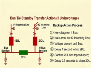
Automatic Bus Transfer Scheme
Outline and Installation Dimensions of Bus Tie Automatic Bus Transfer


FAQ
Q:What is a Automatic Bus Transfer Switch?
A:A standby power transfer device is an automatic mechanism that switches to the standby power source when the main power supply is interrupted due to a fault or other reasons, thereby ensuring uninterrupted power supply. It is a type of relay protection product used in substations.
Q:How to Select an Automatic Control Relay?
A:Select an automatic transfer switch (ATS) with correct operating logic that coordinates with upstream and downstream protection systems and meets the required operating time criteria, based on the system voltage level, main bus configuration, and type of standby power source (feeder, bus tie, or transformer).
2 reviews for Automatic Bus Transfer Switch 83B
Related products


High Quality
Stable performance, reliable design, ensuring safe operation for power system protection and grid stability.
Fast Delivery
Timely delivery to support your urgent orders and project schedules efficiently and professionally at any time.
Best Warranty
Professional Warranty: Reliable after-sales support for stable relay protection and long-term customer satisfaction.
xiao zhang –
Reliable automatic bus transfer switch, fast logic switching, stable operation for substation backup power, ideal for overseas projects.
Jack –
Has been running normally since put into operation — truly a reliable product.