-
Leon Zhang sales consultant
-
Email: zxl635973785@gmail.com
-
Phone/WhatsApp: +86 13655813266


ASK-441H Intelligent Voltage Selection Relay
Voltage Selection Relay Overview
The ASK-441H Digital PT Control and Switching Unit, as a subsystem of the substation integrated automation system, primarily provides automatic and remote switching functions for two sets of busbar PTs.
Product Functions (ANSI):
27/59/60+85/85/27/59N/60
Communication Mode:Optional:
RS-485, CAN bus, Ethernet, IEC 60870-5-103 (IEC-103),IEC 61850
In-house Factory & Technical Team, OEM ODM Custom Electrical Equipment
Send your requirements, we will quote for you within 12 hours
Description
Voltage Selection Relay Overview
- The ASK-441H Digital PT Control and Switching Unit, as a subsystem of the substation integrated automation system, primarily provides automatic and remote switching functions for two sets of busbar PTs.
- This PT Selection Unit, also known as VT Selection Relay, can automatically switch to the other set of PTs when one set is taken out of service, thereby preventing the low-voltage protection of protection devices from unnecessary tripping. It also supports parallel operation of PTs through remote control or manual operation.
Protection Features of Voltage Transformer Switching Device
- PT automatic switching function
- PT remote control switching function
- Overvoltage alarm
- Undervoltage alarm
- Zero-sequence overvoltage alarm
- Busbar PT breakage detection
- Insulation monitoring function
Communication Mode
- Optional: RS-485, CAN bus, Ethernet, IEC 60870-5-103 (IEC-103),IEC 61850
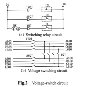
Working Principle of Intelligent Voltage Selection Relay
Main Functional Specifications
- Protection response time (including the response time of the output relay): Average error in response time: not more than 35 ms;
- Precision operating range: Minimum precision current: 0.08 In, Maximum precision current: 20 In
- Current setting error: When the current exceeds 1.00 A, the error shall not exceed ±2.5%; Voltage setting error: shall not exceed ±3%
- Measurement accuracy: Current (I)/Voltage (U): Class 0.2; Power (P)/Reactive power (Q): Class 0.5
- Remote signal resolution: no more than 2 ms
Event Logging, Fault Recording
- The recorded events include protective action events and device malfunctions;
- Record the type of protection trip, the time of the trip, and the operating parameters at the time of the trip;
- The fault recording data includes: the time of the protection operation, the type of protection operation, and the rms values before and after the recording was initiated;
- Data length of the fault recording: 2 cycles before the fault and 4 cycles after the fault;
- The SOE can retain 48 sets of data after a power loss, and the fault report can retain 16 sets of data after a power loss.
Fixed Values of Secondary Voltage Selection Device
| No. | Display Name | Range | Step | Remarks |
|---|---|---|---|---|
| 1 | Bus I Overvoltage Protection Setting | |||
| 1.1 | Bus I Overvoltage Protection | 1/0 | — | Overvoltage protection enable(1) / disable(0) |
| 1.2 | Overvoltage Time Delay | 0~120.00s | 0.01s | — |
| 1.3 | Overvoltage Setting Value | 5~120V | 0.01V | — |
| 2 | Bus I Undervoltage Protection Setting | |||
| 2.1 | Bus I Undervoltage Protection | 1/0 | — | Undervoltage protection enable(1) / disable(0) |
| 2.2 | Undervoltage Time Delay | 0~120.00s | 0.01s | — |
| 2.3 | Undervoltage Setting Value | 5~100V | 0.01V | — |
| 3 | Bus I Zero-sequence Overvoltage Setting | |||
| 3.1 | Bus I Zero-sequence Voltage Protection | 1/0 | — | Zero-sequence overvoltage protection enable(1) / disable(0) |
| 3.2 | Zero-sequence Voltage Time Delay | 0~120.00s | 0.01s | — |
| 3.3 | Zero-sequence Voltage Setting Value | 5~120V | 0.01V | — |
| 4 | Bus II Overvoltage Protection Setting | |||
| 4.1 | Bus II Overvoltage Protection | 1/0 | — | Overvoltage protection enable(1) / disable(0) |
| 4.2 | Overvoltage Time Delay | 0~120.00s | 0.01s | — |
| 4.3 | Overvoltage Setting Value | 5~120V | 0.01V | — |
| 5 | Bus II Undervoltage Protection Setting | |||
| 5.1 | Bus II Undervoltage Protection | 1/0 | — | Undervoltage protection enable(1) / disable(0) |
| 5.2 | Undervoltage Time Delay | 0~120.00s | 0.01s | — |
| 5.3 | Undervoltage Setting Value | 5~100V | 0.01V | — |
| 6 | Bus II Zero-sequence Overvoltage Setting | |||
| 6.1 | Bus II Zero-sequence Voltage Protection | 1/0 | — | Zero-sequence overvoltage protection enable(1) / disable(0) |
| 6.2 | Zero-sequence Voltage Time Delay | 0~120.00s | 0.01s | — |
| 6.3 | Zero-sequence Voltage Setting Value | 5~120V | 0.01V | — |
| 7 | PT Switching Setting | |||
| 7.1 | PT Automatic Switching | 1/0 | — | PT automatic switching permit(1) / inhibit(0) |
| 7.2 | PT Remote Switching | 1/0 | — | PT remote switching permit(1) / inhibit(0) |
| 7.3 | PT Manual Switching | 1/0 | — | PT manual switching permit(1) / inhibit(0) |
| 7.4 | PT Switching with Bus Coupler Judgement | 1/0 | — | Judge bus coupler position(1) / not judge(0) |
| 7.5 | PT Switching without Bus Voltage Judgement | 1/0 | — | Not judge bus voltage(1) / judge bus voltage(0) |
| 7.6 | PT Switching without Position Judgement | 1/0 | — | Not judge position(1) / judge position(0) |
| 7.7 | Switching Time Delay | 0~120.00s | 0.01s | — |
| 7.8 | Exit Time Delay | 0~120.00s | 0.01s | — |
| 7.9 | Busbar Voltage Threshold | 5~120V | 0.01V | — |
| 8 | General Setting | |||
| 8.1 | Bus I PT Fuse Failure Monitoring | 1/0 | — | Bus I PT broken line monitoring enable(1) / disable(0) |
| 8.2 | Bus II PT Fuse Failure Monitoring | 1/0 | — | Bus II PT broken line monitoring enable(1) / disable(0) |
| 8.3 | Bus I Insulation Monitoring | 1/0 | — | Bus I insulation monitoring enable(1) / disable(0) |
| 8.4 | Bus II Insulation Monitoring | 1/0 | — | Bus II insulation monitoring enable(1) / disable(0) |
| 8.5 | B17 as Maintenance Plate | 1/0 | — | B17 maintenance plate enable(1) / disable(0) |
| 8.6 | Negative Sequence Voltage | 5~120V | 0.01V | — |
| 8.7 | Mutation Starting | — | — | — |
Outline and Installation Dimensions


FAQ
Q1:What’s core function of this Intelligent Voltage Selection Relay?
A:Automatically switch secondary PT voltage between working & standby PT to ensure intact voltage supply for measuring, metering and protection loops.
Q2:Can it detect PT broken wire fault?
A:Yes, built-in PT disconnection detection, output alarm signal and avoid protection false tripping caused by missing voltage.
Q3:Available communication interfaces?
A:Optional RS485, Ethernet and IEC103 for remote status monitoring and fault message upload.
Q4:Which application scenarios does it fit?
A:Widely used in substation PT cabinet, switchgear and distribution automation system for domestic and overseas power projects.
Q5:Does it support manual/automatic switching mode?
A:Dual modes available: auto logic switching under normal condition and manual forced switch for onsite maintenance test.
2 reviews for ASK-441H Intelligent Voltage Selection Relay
Related products


High Quality
Stable performance, reliable design, ensuring safe operation for power system protection and grid stability.
Fast Delivery
Timely delivery to support your urgent orders and project schedules efficiently and professionally at any time.
Best Warranty
Professional Warranty: Reliable after-sales support for stable relay protection and long-term customer satisfaction.
xiao zhang –
This intelligent voltage selection relay delivers stable PT switching logic with high sampling precision. It prevents PT open-circuit mal-operation and supports standard communication for remote monitoring, ideal for substation automation upgrade projects globally.
Jack –
Low temperature rise, safe for long-term operation — worth praising.