-
Leon Zhang sales consultant
-
Email: zxl635973785@gmail.com
-
Phone/WhatsApp: +86 13655813266


ASF-442H Advanced Voltage and Frequency Control Relay
Overview of Voltage and Frequency Control System
The ASF-442H Frequency and Voltage Stabilization Control Unit is a core device for voltage and frequency control in power system, control of frequency and voltage, and professional frequency and voltage control.
Communication Mode:Optional: RS-485, CAN bus, Ethernet, IEC 60870-5-103 (IEC-103),IEC 61850
In-house Factory & Technical Team, OEM ODM Custom Electrical Equipment
Send your requirements, we will quote for you within 12 hours
Description
Overview of Voltage and Frequency Control System
- The ASF-442H Frequency and Voltage Stabilization Control Unit is a core device for voltage and frequency control in power system, control of frequency and voltage, and professional frequency and voltage control.
- It is designed to disconnect specified power equipment such as transmission lines or unit transformers when system frequency or voltage drops, thereby ensuring the safe and stable operation of the power grid.
- It is a load shedding controller.Its main functions include under frequency load shedding and under frequency and undervoltage load shedding, covering low-frequency/low-voltage disconnection, high-frequency/low-voltage disconnection, and rapid startup of standby units under low-frequency/low-voltage conditions, as well as low-frequency detection, low-voltage detection, over-frequency detection, over-voltage detection, and reverse power detection.
Features
Protection Functions
| Item | Description |
|---|---|
| Five-stage low-frequency protection | Configurable slip lockout and low-voltage lockout;
Low-frequency derating supports trip output or alarm output |
| Five-stage low-voltage derating | Five-level low voltage derating function |
| Over-frequency protection | Configurable low-voltage lockout;
Over-frequency derating supports trip output or alarm output |
Communication Functions
| Item | Description |
|---|---|
| Communication Modes | RS-485, CAN, Wired Ethernet, Fiber-optic Ethernet (specify when ordering) |
| Data Upload | Transmits real-time measurement data, waveform data, faults, alarm signals, protection settings, configurations and coefficients. Supports remote online modification of protection settings and enabling/disabling of protection functions. |
| Command Reception | Receives commands from upper system: time synchronization, parameter adjustment, data read and write |
Main Functional Specifications
| Item | Specification |
|---|---|
| Protection response time | Average error ≤ 35 ms (including output relay response time) |
| Precision operating range | 0.08 In ~ 20 In |
| Current setting error | ≤ ±2.5% (for current above 1.00 A) |
| Voltage setting error | ≤ ±3% |
| Measurement accuracy | Current & Voltage: Class 0.2
Active Power & Reactive Power: Class 0.5 |
| Remote signal resolution | ≤ 2 ms |
Event Logging, Fault Recording
| Item | Description |
|---|---|
| Event Logging | Records protection trips, device faults, trip types, time and operating parameters |
| Fault Recording | Stores protection action time, action type and RMS values before & after trigger |
| Recording Duration | 2 cycles before fault, 4 cycles after fault |
| Power-off Data Storage | 48 SOE records, 16 fault reports |
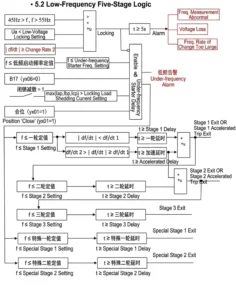
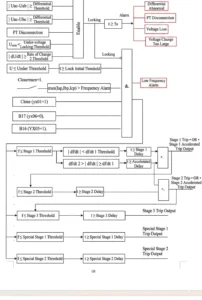
Action Logic Diagram
Setting Table
| No. | Display Name | Range | Step | Remark |
|---|---|---|---|---|
| 1 | Under-frequency Stage 1 Setting | |||
| 1.1 | Under-frequency Stage 1 Enable/Disable | 1/0 | — | Undervoltage protection: Enable(1) / Disable(0) |
| 1.2 | Stage 1 Time Delay | 0~120.00s | 0.01s | |
| 1.3 | Stage 1 Setting Value | 46~50.00Hz | 0.01Hz | |
| 2 | Under-frequency Stage 2 Setting | |||
| 2.1 | Under-frequency Stage 2 Enable/Disable | 1/0 | — | Undervoltage protection: Enable(1) / Disable(0) |
| 2.2 | Stage 2 Time Delay | 0~120.00s | 0.01s | |
| 2.3 | Stage 2 Setting Value | 46~50.00Hz | 0.01Hz | |
| 3 | Under-frequency Stage 3 Setting | |||
| 3.1 | Under-frequency Stage 3 Enable/Disable | 1/0 | — | Undervoltage protection: Enable(1) / Disable(0) |
| 3.2 | Stage 3 Time Delay | 0~120.00s | 0.01s | |
| 3.3 | Stage 3 Setting Value | 46~50.00Hz | 0.01Hz | |
| 4 | Special Under-frequency Stage 1 | |||
| 4.1 | Stage 1 Time Delay | 0~120.00s | 0.01s | |
| 4.2 | Stage 1 Setting Value | 46~50.00Hz | 0.01Hz | |
| 5 | Special Under-frequency Stage 2 | |||
| 5.1 | Stage 2 Time Delay | 0~120.00s | 0.01s | |
| 5.2 | Stage 2 Setting Value | 46~50.00Hz | 0.01Hz | |
| 6 | General Under-frequency Setting | |||
| 6.1 | Startup Time Delay | 0~120.00s | 0.01s | |
| 6.2 | Startup Setting Value | 46~50.00Hz | 0.01Hz | |
| 6.3 | Acceleration Time Delay | 0~120.00s | 0.01s | |
| 6.4 | Df/dt1 | 1.0Hz/s~9.9Hz/s | 0.1Hz/s | Slip blocking setting value |
| 6.5 | Df/dt2 | 1.0Hz/s~9.9Hz/s | 0.1Hz/s | Slip blocking setting value |
| 7 | Over-frequency Protection | |||
| 7.1 | Over-frequency Protection Enable/Disable | 1/0 | — | Over-frequency protection: Enable(1) / Disable(0) |
| 7.2 | Over-frequency Trip Enable/Disable | 1/0 | — | Over-frequency: Trip(1) / Alarm(0) |
| 7.3 | Undervoltage Blocking Over-frequency | 1/0 | — | Undervoltage blocking: Enable(1) / Disable(0) |
| 7.4 | Over-frequency Time Delay | 0.1~120.00s | 0.01s | |
| 7.5 | Over-frequency Setting Value | 50~54Hz | 0.01Hz | |
| 8 | Undervoltage Stage 1 Setting | |||
| 8.1 | Undervoltage Stage 1 Enable/Disable | 1/0 | — | Undervoltage protection: Enable(1) / Disable(0) |
| 8.2 | Stage 1 Time Delay | 0~120.00s | 0.01s | |
| 8.3 | Stage 1 Setting Value | 0~100.00V | 0.01V | |
| 9 | Undervoltage Stage 2 Setting | |||
| 9.1 | Undervoltage Stage 2 Enable/Disable | 1/0 | — | Undervoltage protection: Enable(1) / Disable(0) |
| 9.2 | Stage 2 Time Delay | 0~120.00s | 0.01s | |
| 9.3 | Stage 2 Setting Value | 0~100.00V | 0.01V | |
| 10 | Undervoltage Stage 3 Setting | |||
| 10.1 | Undervoltage Stage 3 Enable/Disable | 1/0 | — | Undervoltage protection: Enable(1) / Disable(0) |
| 10.2 | Stage 3 Time Delay | 0~120.00s | 0.01s | |
| 10.3 | Stage 3 Setting Value | 0~100.00V | 0.01V | |
| 11 | Special Undervoltage Stage 1 Setting | |||
| 11.1 | Special Undervoltage Stage 1 Enable/Disable | 1/0 | — | Undervoltage protection: Enable(1) / Disable(0) |
| 11.2 | Stage 1 Time Delay | 0~120.00s | 0.01s | |
| 11.3 | Stage 1 Setting Value | 0~100.00V | 0.01V | |
| 12 | Special Undervoltage Stage 2 Setting | |||
| 12.1 | Special Undervoltage Stage 2 Enable/Disable | 1/0 | — | Undervoltage protection: Enable(1) / Disable(0) |
| 12.2 | Stage 2 Time Delay | 0~120.00s | 0.01s | |
| 12.3 | Stage 2 Setting Value | 0~100.00V | 0.01V | |
| 13 | General Undervoltage Setting | |||
| 13.1 | Startup Time Delay | 0~120.00s | 0.01s | |
| 13.2 | Startup Setting Value | 0~100.00V | 0.01V | |
| 13.3 | Acceleration Time Delay | 0~120.00s | 0.01s | |
| 13.4 | Voltage Difference Setting Value | 0~100.00V | 0.01V | |
| 13.5 | dv/dt1 | 1.0V/s~9.9V/s | 0.1V/s | Voltage difference blocking setting value |
| 13.6 | dv/dt2 | 1.0V/s~9.9V/s | 0.1V/s | Voltage difference blocking setting value |
| 14 | Overvoltage Protection | |||
| 14.1 | Overvoltage Protection Enable/Disable | 1/0 | — | Overvoltage protection: Enable(1) / Disable(0) |
| 14.2 | Overvoltage Trip | 1/0 | — | Trip(1) / Alarm(0) |
| 14.3 | Overvoltage Time Delay | 0~120.00s | 0.01s | |
| 14.4 | Overvoltage Setting Value | 0~120.00V | 0.01V | |
| 15 | General Setting | |||
| 15.1 | Under-current Blocking Load Shedding | 1/0 | — | |
| 15.2 | PT Disconnection | 1/0 | — | PT disconnection detection: Enable(1) / Disable(0) |
| 15.3 | 3P4W Voltage Wiring | 1/0 | — | 3P4W(1) / 3P3W(0) |
| 15.4 | Measuring Voltage 380V | 1/0 | — | 380V(1) / 100V(0) |
| 15.5 | Current Rated 1A | 1/0 | — | 1A(1) / 5A(0) |
| 15.6 | Blocking Load Shedding Current | 0.5~6A | 0.01A | Secondary rated current |
| 15.7 | Undervoltage Setting Value | 0~100.00V | 0.01V | |
| 15.8 | Undervoltage Blocking Value | 0~100.00V | 0.01V | Undervoltage setting for over-current blocking |
Outline and Installation Dimensions


FAQ
Q1: What is the core function?
A: Shed non-priority loads by stages when grid frequency or voltage drops below setting values to pull grid voltage and frequency back to normal and avoid blackout.
Q2: Does it support multi-stage setting?
A: Yes, multiple independent stages for under-frequency and under-voltage respectively with separate delay and threshold configuration.
Q3: Can it avoid mis-operation?
A: Equipped with blocking logic for short-circuit transient drop, CT/PT failure locking to prevent incorrect load shedding.
Q4: Communication options available?
A: Optional RS485, Ethernet, IEC103 for remote parameter setting and fault record upload.
Q5: Typical application sites?
A: Substations, distributed power stations and industrial power networks for domestic and overseas power projects.
Q:How Under-Voltage Load Shedding Controls Circuit Breakers?
Fault disconnection involves rapidly disconnecting the faulted area from the power grid upon detection of a grid fault or instability to isolate the fault and prevent the impact from spreading;
Emergency frequency and voltage control, on the other hand, involves gradually shedding part of the load or adjusting generation output according to a multi-round strategy when a power deficit causes frequency or voltage deviations, thereby restoring system balance.
The former focuses on fault isolation, while the latter focuses on rebalancing supply and demand.
2 reviews for ASF-442H Advanced Voltage and Frequency Control Relay
Related products

")


High Quality
Stable performance, reliable design, ensuring safe operation for power system protection and grid stability.
Fast Delivery
Timely delivery to support your urgent orders and project schedules efficiently and professionally at any time.
Best Warranty
Professional Warranty: Reliable after-sales support for stable relay protection and long-term customer satisfaction.
xiao zhang –
Stable multi-stage shedding logic for system frequency/voltage collapse prevention, flexible parameter setup and standard communication, widely applied in grid substations worldwide.
Jack –
Easy to set, clear logic, and no issues since commissioning.